Dual RCD Consumer Units

Joined
29 Jun 2006
Messages
396
Reaction score
20
Location
Middlesbrough
Country
United Kingdom
I've just come across one of these for the first time when it was wrongly delivered for two C&G 2392 boards I am constructing.

Are these what everyone is installing now?

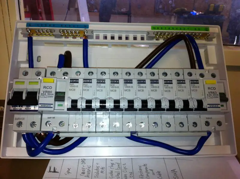
Both RCDs are 30mA but rated at 63A and 80A.

The course spec says it requires a split load board with a ring final circuit and a cooker on the RCD protected side and a 2 way lighting circuit and a 20A radial to a single socket (labelled "Not for general use").

The course is only just over two years old so would it not have one of these supposed "17th Edition Dual RCD unit " boards?
 
Sponsored Links
Well how is everyone splitting the circuits?

63A
Lighting
Cooker
Fridge Freezer
Radials to Fixed Appliances

80A
Shower
Ring final ccts

Or other?
 
I think the 'cheaper' dual boards have a 63 and an 80, but higher spec ones have 2x 80's?? IIRC

I tend to do as follows:

Main switch
rcbo (or mcb if appropriate) for lights where the DB is located

RCD1
Sockets up
lights down

RCD2
Sockets down
Lights up

Plus fit the rest of the stuff to give a reasonable load balance and sensible configuration. I often put outside sockets/flower border lights/pond pumps on an rcbo after the main switch as these are so prone to tripping.

The reason for the arrangement above is so that if RCD1 trips then you can at least plug in some lights on the socket circuit on the other RCD.

SB
 
Sponsored Links
the main considerations are (AFAIK)
seperation of the following circuits

bathroom light - shower
lights - sockets - per floor
cooker - kitchen sockets

security - not usually on a 30Ma controlled circuit

the best example i've seen is the wylex brochure which shows the circuits

the main idea is that only half a room is affected as said above and that a light will not fail in the event of a shower etc failure.
 
So it sounds like there is some modification going on then other wise why would RCBO's be installed (in Sparkybird's reply) or

Security circuits be non-rcd protected (in kevindgas reply)

It sounds like you are creating a monster (cutting busbar) How do you get a non-rcd protected neutral bar? when there are only two in there? :D

And I assume that the invention of these is so that we don't have to bury everything more than 50mm from the surface of the wall?
 
If all cables were 50mm deep there would be no strength left in the walls of the property, it would be like a house of cards.
 
Maybe we're talking about diff boards? I install flexible dual splits 10 or 15 ways. I generally configure a 10 way as 2 non rcd, then 4 each on the 2 RCD's. There are 3 N bars on these boards.....

I always have some non RCD protected circuits eg SWA to garage - you don't want to have to come back to the house if that trips... plus as mentioned a critical lighting circuit (ie the one in the DB cupboard!) on rcbo.

Maybe I'm just kind to my customers!

SB
 
plus as mentioned a critical lighting circuit (ie the one in the DB cupboard!) on rcbo.
Install a non-maintained luminaire connected via a switch mounted upside down, so flicking down actually breaks the circuit and it illuminates.
 
Like your style ban....

But not always appropriate in a domestic setting, at least not the ones I normally do!
 
Why not just get one that has maintained mode and wire teh switch to bring that on, they arn't much more expensive if we are talking standard 8w bulkhead things :D
 
So it sounds like there is some modification going on then other wise why would RCBO's be installed (in Sparkybird's reply) or

Security circuits be non-rcd protected (in kevindgas reply)

It sounds like you are creating a monster (cutting busbar) How do you get a non-rcd protected neutral bar? when there are only two in there? :D

And I assume that the invention of these is so that we don't have to bury everything more than 50mm from the surface of the wall?

like sparkybird says the boards we use have 3 neutral bars, wylex show 3 sections in their diagrams on their brochure
 
Ahh OK. Wonderful thanks.

So it turns out I can modify this board, remove an RCD and use the traditional split load board and have 5 non-rcd and 5 rcd protected.

The way the busbars are set out though mean I have a question.

The RCDs will have to be switched around. Both are identical apart from their rating and the live terminal label.. infact I'll upload the picture (all connections are factory made btw)


You can see that the live terminal is on the left on one RCD and on the right on the other. I thought it mattered what side the live was connected on due to the test button resistor. Am I right?
 

DIYnot Local

Staff member

If you need to find a tradesperson to get your job done, please try our local search below, or if you are doing it yourself you can find suppliers local to you.

Select the supplier or trade you require, enter your location to begin your search.


Are you a trade or supplier? You can create your listing free at DIYnot Local

 
Sponsored Links
Back
Top