EM stop diagram needed

Joined
10 Aug 2004
Messages
444
Reaction score
23
Location
Staffordshire
Country
United Kingdom
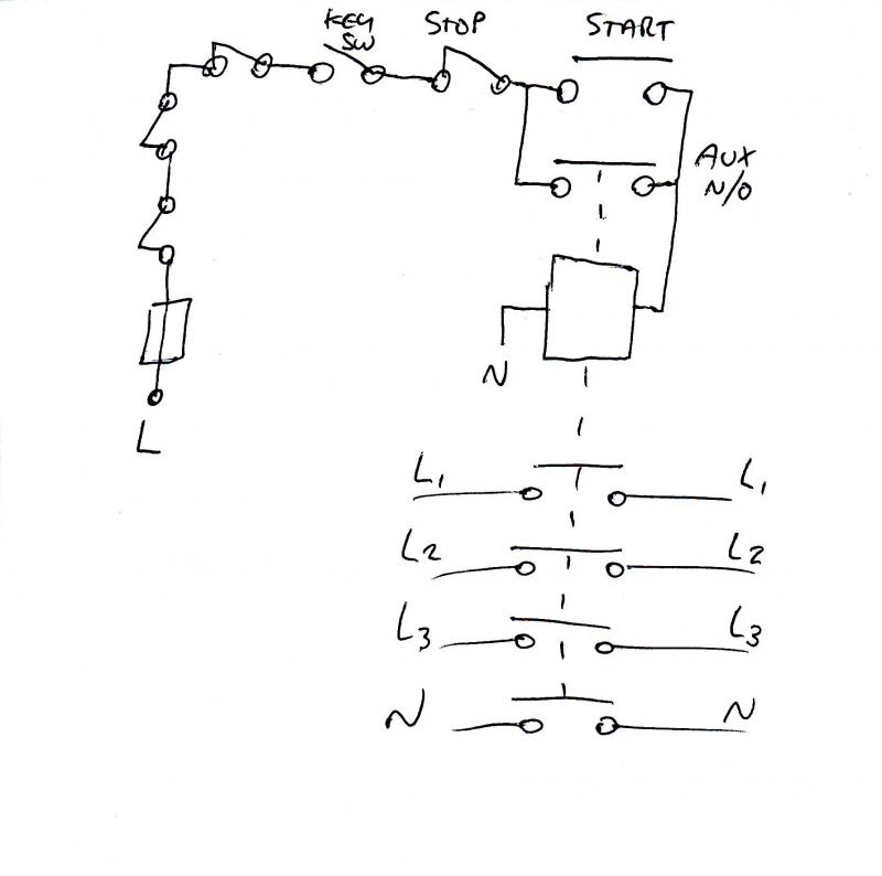
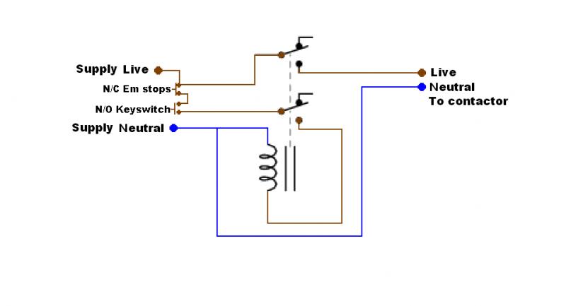
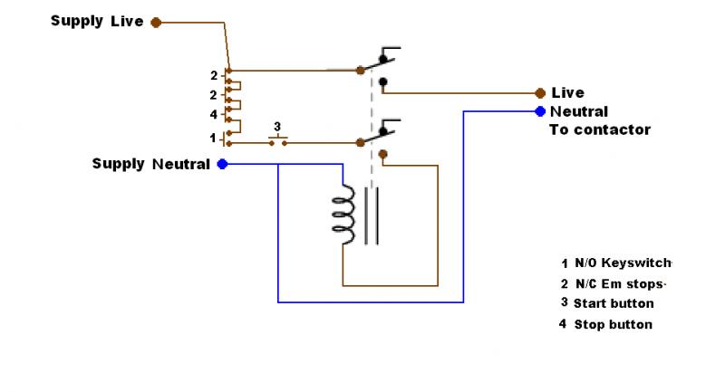
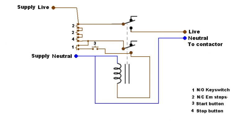
Hi all went to a job to day to re-instate the emergency power off contactors to two dsiboards in a school. They operate machinery so when an e stop is hit they need to open. I have done the mains power side and connected the coil up temporarily to energise it . The problem i am having is the E stop circuit is an old part of the system and so i need to interface this with my contactors. The E stop buttons are non latching n/c and there is a keyswitch in series with these as an isolator to stop the power being used if nobody is there. these are all wired in a loop from an enclosure. Also we have a start and stop button which have both n/c and n/o contacts and are non latching aswell. These are wired as a common linked between the two switches and then a n/c and a n/o back to the enclosure so 3 cores in total . then i have the 230v live from the control circuit ,with a neutral and also the live to operate the contactors coil to pull the 100a contactors in. I believe i need to use a latching relay to make this all work correctly but could someone pont me in the direction of a diagram , and perhaps the RS part number for the correct relay .

Chhers in advance
Nick
 
Sponsored Links
Just to clarify, how many poles are your contactor(s)?

Is there, or are you looking to install a relay to control the existing contactors?


<edit> too slow again :LOL:
 
Hi RF the conatctors isolating the boards are 4 pole, but the control cct is fed from the busbars via a fuse spur.there is no auxillaries on the main conatctors, and space is very tight to fit any to them, so i really need a relay to add to the enclosure with all my cables in it.

Any help ,much appreciated

Nick
 
Sponsored Links
Is there no space to fit an aux block on the front?
If not you will need to have a contactor setup as you would for a DOL with the main contactor being fed from a N/O circuit via this DOL contactor.
 
the contactors we have used are the cheap nasty newlec ones which have abb contactors in them but they have their auxilliaries on the side of them . I would be intersted to see how you could do it with auxilliary contacts aswell though for future reference.

Nick
 
Not sure if a relay would be up to the job - we have always used contactors. This is how it would be done using the aux block.
(The N/C contacts to the LHS of the drawing are the emergency stop buttons)
 
Cheers for that RF, the existing system used to have a stop and a strt button to reset it if the em stops were pushed as they were non latching, in your pic how would the sytem be reset if the em is pushed?


Nick
 
Jeez, do you want me to come and do the job for you :evil:

I drew the diagram with the keyswitch as a non latching switch. This is then used effectively as the start button.

Hows that then?


:LOL:
 
well if you could come and do the job for me would save me a load of trouble LOL, Just kidding, i am very grateful for your help with this, as i have been dropped in it by the boss, and the tw## who ripped it all out in the first place. I will use your diagram and connect it to the letter and will hopefully be the hero and save the day LOL, (witha bit of help from my friends on here of course)

Thanks again

If you ever need assistance with anything that i might know about just give me a holler

Nick
 
The start N/O pb needs to be in parallel with the N/O contact in order for it to energize the coil when pressed and latch, as drawn in the pic I posted above ;)
 

DIYnot Local

Staff member

If you need to find a tradesperson to get your job done, please try our local search below, or if you are doing it yourself you can find suppliers local to you.

Select the supplier or trade you require, enter your location to begin your search.


Are you a trade or supplier? You can create your listing free at DIYnot Local

 
Sponsored Links
Back
Top