

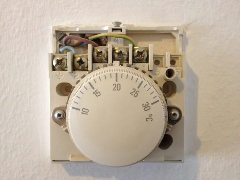
I am looking to replace an old Honeywell T40, but I am a little concerned how it is wired currently.
I believe terminals 3 and 1 are connected the wrong way around.
Assuming red is live and yellow/green is switched live.
Any opinions?
How could I test it?
Thanks[/img]
I believe terminals 3 and 1 are connected the wrong way around.
Assuming red is live and yellow/green is switched live.
Any opinions?
How could I test it?
Thanks[/img]