MK Fully populated with RCBO's (x15)

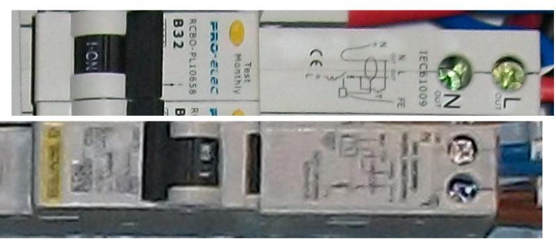
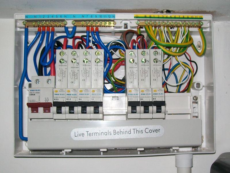
Not very pretty, either the equipment or the installation. This is Pro-Elec as sold by CPC - and if you pick the timing, you can get an RCBO for as little as £10. Needless to say, I bought spares of each size - and I've used one (one was DOA when my mate had his bungalow done).
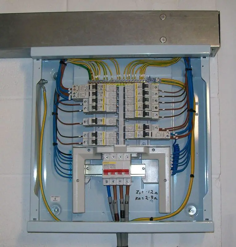
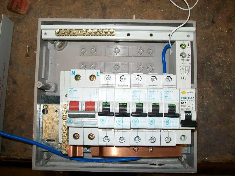
You can see at the bottom where the flimsy case has flexed where the conduit goes in, and what you can't see is how flimsy the breaker mounting rail is. However, the sparky did say it wasn't the worst he'd worked with :eek:
I deliberately chose a unit larger than needed - partly to allow for extra circuits, but more to allow extra space to work in !
 
Sponsored Links
So are a lot of other brands. AFAICT, it's no so much that these are huge, it's just that some others have been made smaller over the years.

This is one I spotted on a customer's site where I was doing some networking. I reckon the extra length due to the RCBO bit is around the same as the Pro-Elec ones I've got - but there's a lot more room in the board for them !
Edit: Shows the art of neat installation is not dead, but then the guy blew it by
a) Grabbing the huge section in the dado trunking for just a single RFC and an earth bonding cable - leaving me with a space too small for my data cables. When he said it must be great to have someone else do all the containment, it was hard not to tell him what I really think about following dipsticks who haven't got a clue about data cables or space requirements.
b) Justifying the above on the grounds that "it must be done that way". He genuinely believed that it's a requirement that the mains go in the central section of the trunking :rolleyes:
 
those Square D ones are nowhere near as big as those Pro-Elec ones though. Having the live and neutral terminals side by side helps rather than on top of each other (Schneider ones are the same too)
 
Sponsored Links
Yeah, but they are cheap :rolleyes:
This is what they look like side by side and scaled to the same size,
I agree about the side-by-side screws, those deeply recessed neutrals are a pain (and my insulated driver doesn't fit down the hole). I had to take one out in the flat when I found a high rn on one of the RFCs - and it was "not the easiest" job I've ever done.

Needless to say, once I'd seen the size, I quickly dropped one idea I had to avoid the notification requirements of changing the CU. Don't think I'd have managed to wire them in that :eek:
 
Sticking to typical consumer units, I know "industrial" boards can be significantly bigger and the considerations different ...

I guess the first thing to consider is that you won't be loading them all to full capacity at once. Then you need to consider that (for all the ones I've seen) the neutral is the same size regardless of breaker capacity - so a B6 has the same size neutral as a B40 or C40 (or whatever size they go up to).
And then at one end of the cable, it's mechanically fixed into a big lump of bare copper - so heat can dissipate along the cable as well as through it's insulation to air.

So while you might load one or two up (say having an electric shower while the Sunday lunch is cooking), the bundle is going to be fairly large and the effective surface area available to dissipate heat will be significant.
That's the case for a domestic install, I suppose it's possible that a commercial installation could have a higher loading - but then you'll still (if it's been done properly) be limited to the total load limit (typically 100A ?) for the whole board.
Either way, you've a max of (say) 100A spread between a minimum of about 3off neutral tails - all of which are 4 or 6mm2 (?). 3 tails bundled is little different to a 3 core/3P cable, or 3xsingles in a small conduit. Once you increase the number of breakers the load is spread across, then the size of the bundle (both physical size and copper CSA) increases.
 
I would be grateful for comment / advice re: the attached photo.

Please be aware of the following:
1. The box is not distorted - it is a new MK metal one - image distorted by camera.
2. The single cable is there to 'test' accessibility.
3.As you can see this is not wired / energised - this will be undertaken by my electrician - he has agreed for me to undertake this (for learning/ save some costs) - and will be subject to his approval and change.
4. There have been threads on shortening neutral tails with varying opinions - so is the situation here daft / acceptable / good?
5. The label is only there to invite comment on loading / distribution. ie is it good practice to mix loadings?

With due respect to all contributors, I would be most grateful for comments from experienced professional (qualified) domestic electricians.

For those of you who 'think' I am intending to install this myself - I am not - I am trying to learn and get feedback on what is good practice so I can discuss the pros and cons with my electrician. If I were him I would cut the neutrals to make life easier, but the collective wisdom here may support or argue against that.

BTW - IF these are only every designed to fit in domestic CU's why do MK make them with such long tails, or are they used in industrial boards?

Thank you for your time and comments - this is a great forum. :D

View media item 60838 [/img]
 
That's nice an neat, but think ahead ...
Imagine what it will look like with all the wiring installed. Now change an RCBO - I think you'll find it virtually impossible without serious disturbance. The neutrals might be OK if you haven't put a lot of cables down the left hand side, but the earth tail will be a different matter. Those RCBOs aren't much (if any) smaller than the ProElec ones I posted a picture to earlier, and they are "fiddly" to wire with the neutral terminal so far down into the unit. You'll find the space above the breakers will disappear very quickly - IMO the box needs to be several inches taller above the breakers but few manufacturers seem to have taken on board that RCBOs are bigger than MCBs (one wonders if their designers ever actually use the stuff !).

I'd shorten the tails, there's no problem there - but I leave some spare length in case a breaker gets moved. For both neutral and earth tails, you really need a bootlace ferrule on the end as the terminals aren't very good with stranded cable - and for the earth you'll be sharing a terminal with a solid wire (or two) from the outgoing circuit. From a purely "how best to install it now" perspective, you'd shorten to the neutral and earth tails to just the right length - and the same with the wiring that goes into it. That gives you now margin for "oops, I need an extra inch" - but all those spare inches take up a lot of room in a not very big box.

The Pro-Elec ones come with long tails as well. I'm not quite sure why they are so long, but I think you have the right answer. Some industrial boards can be quite large, and I think most electricians would be "quite vocal" if they had to start extending tails off breakers. I'm not aware of Pro-Elec doing anything larger than about an 18 way consumer unit, so I'm sure they could be a bit shorter. On the other hand, they are probably all made in the same Chinese sweatshops and just printed with different labels to suit the customer.

As to which values of breaker to put where, I can't help thinking that's just one of those "we've always done it this way" things now. Some of the older fuse boards only had one position where the largest fuseholder could be fitted. I suspect that is a large part of the "largest by the main switch and work down" practice came from. As for modern consumer units, look at the size of the live bus bar and I can't see any reason you shouldn't have large loads at the opposite end to the main switch. As you can see from the photo I posted, I grouped the breakers into two groups - one group is stuff inside the flat, the other group is stuff outside (garage and outside lights). In part, the gap between them was just to give a bit more room for the cabling (and in part to make identification easier should someone be fumbling around in the dark - it's not in the most accessible of positions).
 
Thank you SimonH2

Is this better / more sensible / acceptable regs wise?

GALLERY]


Despite appearances there is quite a bit of space between the bundles at the bottom to use the conduit cut-outs.

I have separated the Cooker (6mm) and split the sockets. Also, the garage is planned to have 10mm SWA, so plenty of space around to accommodate that.

I have the plastic spacers for the front panel, but are there such things as dummy units or is that silly / fussy? I'm guessing the bus bar ought not be exposed (above its cover).
 
JohnW2 & EFLImpudence

Thank you very much for the suggestions - blanks now in place & more space for the actual wiring. Very tidy and organised - hope my sparky approves!

Kind regards

[/img] View media item 60846
 
JohnW2 & EFLImpudence Thank you very much for the suggestions - blanks now in place & more space for the actual wiring. Very tidy and organised - hope my sparky approves!
As you say, very neat. The only point I'd make it that, if it were me, I would have numbered the circuits according the the 'ways' of the CU (including those which are currently 'spares'), not just the ones currently in use. If you ever use any of those 'spare' ways in the CU, you'll end up with circuits numberd 1½, 4½, 7½ or 8½ :)

Kind Regards, John
 

DIYnot Local

Staff member

If you need to find a tradesperson to get your job done, please try our local search below, or if you are doing it yourself you can find suppliers local to you.

Select the supplier or trade you require, enter your location to begin your search.


Are you a trade or supplier? You can create your listing free at DIYnot Local

 
Sponsored Links
Back
Top