

Hi all,
I'm sure this forum has been inundated with posts about Nest installs, so I apologise if this query has been answered before, but I couldn't see anything as I browsing...
We've recently moved into a house which is relatively new (4 years old), and I'm trying to install a Nest into the system.
To give you a quick summary of the system in place;
* Ideal Logic 15 boiler
* Siemens RWB29 programmer - CH and HW timer
* Siemens RAA20 thermostat
The boiler has 7 connections into it;
* Mains L
* Mains N
* Mains Earth
* sL
* Pump L
* Pump N
* Pump Earth
...this is where I think complicates things...
The pump connections on the boiler aren't wired to the pump (they aren't wire anywhere), even though the Ideal Logic 15 manual states that this should be, otherwise it voids the boiler warranty.
I successfully wired the Nest Heat Link to the boiler;
* Boiler Mains L to Heat Link L
* Boiler Mains N to Heat Link N
* Disconnected sL and replaced with Heat Link 'call-for-heat'
* Jumper between the Heat Link L to Heat Link common
...and replaced the RAA20 thermostat with the Nest thermostat.
I set the programmer to CH 'always on', and everything was great! The Nest successfully called for heat / cancelled heat, the radiators kicked in as before, and the HW sounded like everything was working as before. Excellent.
However, I noticed that the pump was always on, which I believe is because the boiler isn't controlling it, and is instead being turned on / off by the call to heat going through the system to the CH and HW valves.
Not to be outdone, I spent some time noting down all the wiring within the system, and trying to get my head around what goes where, so I can understand where I need to wire the Nest Heat Link so the pump only comes on when the HW calls for it (as before), and Nest calls for CH.
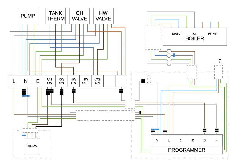
This is where I need assistance. I don't want to wire the Heat Link in the wrong place, and end up with a very expensive paperweight and now CH / HW. I'm guessing I need to wire the call for heat into the orange cable going to the CH valve.
If someone is able to advise on where I need to cable the Heat Link in, that would be fantastic. I've attached the heating diagram, which I hope is 100% correct, but would mean some cables magically change from white to grey in the wall (!?).
I believe it's an S plan system?
The black markers are marker pen 'dashes' on the cables, and the blue markers are blue sleeves on the end of the cables. The small dashed boxes are cables into / out of the area.
The UK Nest install guide is located here:
https://s3.amazonaws.com/support-as...ges/Nest-Thermostat-Installation-Guide-UK.pdf
I'm sure this forum has been inundated with posts about Nest installs, so I apologise if this query has been answered before, but I couldn't see anything as I browsing...
We've recently moved into a house which is relatively new (4 years old), and I'm trying to install a Nest into the system.
To give you a quick summary of the system in place;
* Ideal Logic 15 boiler
* Siemens RWB29 programmer - CH and HW timer
* Siemens RAA20 thermostat
The boiler has 7 connections into it;
* Mains L
* Mains N
* Mains Earth
* sL
* Pump L
* Pump N
* Pump Earth
...this is where I think complicates things...
The pump connections on the boiler aren't wired to the pump (they aren't wire anywhere), even though the Ideal Logic 15 manual states that this should be, otherwise it voids the boiler warranty.
I successfully wired the Nest Heat Link to the boiler;
* Boiler Mains L to Heat Link L
* Boiler Mains N to Heat Link N
* Disconnected sL and replaced with Heat Link 'call-for-heat'
* Jumper between the Heat Link L to Heat Link common
...and replaced the RAA20 thermostat with the Nest thermostat.
I set the programmer to CH 'always on', and everything was great! The Nest successfully called for heat / cancelled heat, the radiators kicked in as before, and the HW sounded like everything was working as before. Excellent.
However, I noticed that the pump was always on, which I believe is because the boiler isn't controlling it, and is instead being turned on / off by the call to heat going through the system to the CH and HW valves.
Not to be outdone, I spent some time noting down all the wiring within the system, and trying to get my head around what goes where, so I can understand where I need to wire the Nest Heat Link so the pump only comes on when the HW calls for it (as before), and Nest calls for CH.
This is where I need assistance. I don't want to wire the Heat Link in the wrong place, and end up with a very expensive paperweight and now CH / HW. I'm guessing I need to wire the call for heat into the orange cable going to the CH valve.
If someone is able to advise on where I need to cable the Heat Link in, that would be fantastic. I've attached the heating diagram, which I hope is 100% correct, but would mean some cables magically change from white to grey in the wall (!?).
I believe it's an S plan system?
The black markers are marker pen 'dashes' on the cables, and the blue markers are blue sleeves on the end of the cables. The small dashed boxes are cables into / out of the area.
The UK Nest install guide is located here:
https://s3.amazonaws.com/support-as...ges/Nest-Thermostat-Installation-Guide-UK.pdf