- Joined
- 11 Oct 2016
- Messages
- 3
- Reaction score
- 0
- Country

Hi all,
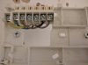
I'm planning to buy a nest v3 and self install if I can. V new existing system was installed in my house about 12 months ago. If it's possible I would wire the heatlink in the utility room where the programmable timer is currently. I am hoping this has the connections I need to do that but coming here for confirmation if possible. As you can see from the photo it has five wires connected to the back plate. Can anyone tell me if those look like all the connections I need to wire in the heatlink, or is it more involved and I would need to do stuff on the other side of the wall in the "boiler room"..?
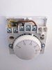
The Honeywell room thermostat (240v I tested it with my meter)... I understand I must have this connection at 12v before I hook up the nest room stat, otherwise I blow it up. There are four wires going into it as you can see in the photo. I believe I jumper something at the heatlink end to enable 12v to the thermostat. If it's not obvious, I'd like to replace that room stat with the nest..
V grateful for any advice on this before I dive in and give it a go or call a pro... (This is a DIY forum right)?") .
.
Will be great if I can do it this way as relatively easy to revert if we leave the house I think and want to take it with us.
Photos attached.
EXISTING SYSTEM summary...
Pressurised system
Greenstar 24i system erp condensing boiler
Pressurised tank with expansion vessel and immersion, thermostatstat on tank...there is a large junction box in this area on opposite side of wall to where the programmable controller is... Haven't opened this up yet, hoping I can tackle it from the controller side.
Honeywell st9400s hot water and CH controller (utility room, on other side of wall from where boiler and tank are).
Honeywell room thermostat (family room)
I'm planning to buy a nest v3 and self install if I can. V new existing system was installed in my house about 12 months ago. If it's possible I would wire the heatlink in the utility room where the programmable timer is currently. I am hoping this has the connections I need to do that but coming here for confirmation if possible. As you can see from the photo it has five wires connected to the back plate. Can anyone tell me if those look like all the connections I need to wire in the heatlink, or is it more involved and I would need to do stuff on the other side of the wall in the "boiler room"..?
The Honeywell room thermostat (240v I tested it with my meter)... I understand I must have this connection at 12v before I hook up the nest room stat, otherwise I blow it up. There are four wires going into it as you can see in the photo. I believe I jumper something at the heatlink end to enable 12v to the thermostat. If it's not obvious, I'd like to replace that room stat with the nest..
V grateful for any advice on this before I dive in and give it a go or call a pro... (This is a DIY forum right)?
.Will be great if I can do it this way as relatively easy to revert if we leave the house I think and want to take it with us.
Photos attached.
EXISTING SYSTEM summary...
Pressurised system
Greenstar 24i system erp condensing boiler
Pressurised tank with expansion vessel and immersion, thermostatstat on tank...there is a large junction box in this area on opposite side of wall to where the programmable controller is... Haven't opened this up yet, hoping I can tackle it from the controller side.
Honeywell st9400s hot water and CH controller (utility room, on other side of wall from where boiler and tank are).
Honeywell room thermostat (family room)