Hi.
I've just purchased a Texecom Premier 24 burglar alarm after a good trawl through these boards and on the recommendation of a sparky mate (who unfortunately lives 60 odd miles away...and I've picked his brains far too much of late!).
This will be the first alarm we, as a family, have owned during the past 15 years (we moved into this current house just over a year ago - it had an alarm installed, but was faulty and at least a couple of decades old).
I unpacked this at the weekend and had a good look at the guides and components. Bit daunted if I'm honest, but after a fair bit of homework, I feel a little better about installing it now (I've actually sunk the remote keypad into the brick wall and have started setting the cable runs in (easier as the ceilings are currently down anyway) albeit I still have a few queries!
If any of the following looks as if I've fallen off the path a little, I'd be most grateful if somebody can provide a little advice and guidance:
Ok - typical 1940's semi-detached property. Hallway, kitchen (with back door) and two reception rooms. I plan to place a door contact only in the hallway (although there is also a window in there, it's a non opening one).
I'll place a PIR in the kitchen, one in the living room and one in the dining room (although I could replace the PIR in the kitchen with a door contact...or both?)
The remote keypad is in the hallway, as is the control panel, although that will be behind/in a cloak cupboard. The control panel will be underneath the consumer unit (I literally have nowhere else to place it) so will take it directly from a 3amp MCB via 1 or 1.5mm T&E (nothing else on the circuit). I did intend to place a 3amp unswitched FCU on that circuit, but can't really see any need to now - feel free to disagree.
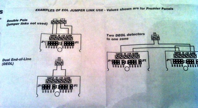
Wiring - I'm probably going to go down the dual end of line route after reading some of the comments on these threads (seems to be more secure). Fortunately, it seems that the PIR's I have already have the 4K7 and a 2K2 'resistors' built in - I'd just have to move them to the correct position and slot in.
I'll probably go along with red and black for power and choose a colour scheme for alarm and tamper.
The bellbox is a little interesting:
I'm assuming that the end of line method can't be used here? I need 5 wires (2x power, 1 tamper, 1 alarm and one for Strb). Hence, I can't use twisted pairs for alarm and tamper here?
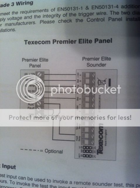
Also, that diagram shows the route for AUX/Fault, but on the actual bellbox there is no connector for this (see pic) - perhaps used on different models?
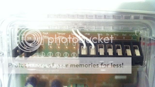
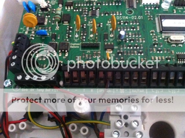
On the actual panel for the bellbox connections, there is a wire already in the 12v port (I assume for the control panel speaker?) - would I merely place my other power (red) wire alongside this from the bellbox?
So far so good?
I'm also a little unsure which cables go into the zone inputs as there are only two per zone [ZONE 1] [ZONE 2] etc. From a a PIR would I fit one pair of twisted wires (DEOL method) into the left (tamper) and the others (alarm) into the right - and then power (red and black) 12v and 0 into both the left and right (no idea which way round)? I read a post on this forum mentioning a 'COM' connection, but I can't locate that anywhere on the panel?
The keypad seems fairly straight forward (linking + - T & R to the corresponding ports on the panel). There is also a Zone 1 and Zone 2 (four ports each split into 2 Alarm and 2 Tamper connections). Not quite sure what these are yet - linking to another keypad? If that's the case, I might drop another 6 core cable in there and send it to our bedroom, just in case we decide on another keypad in the bedroom - sound ok?!
I've actually got the manual online, so I'll have a good read of that later this evening, but I just wanted to see if I'm heading in the right direction.
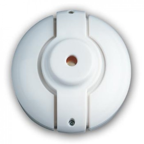
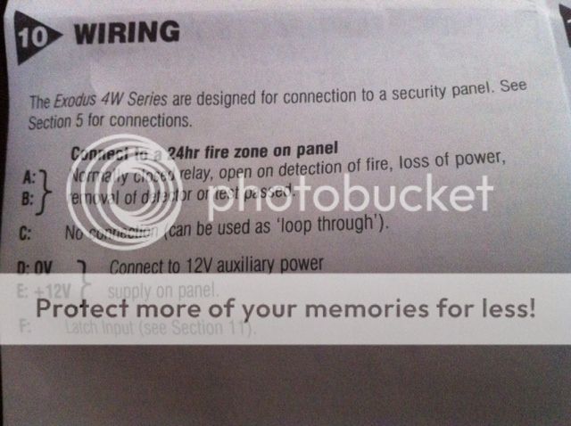
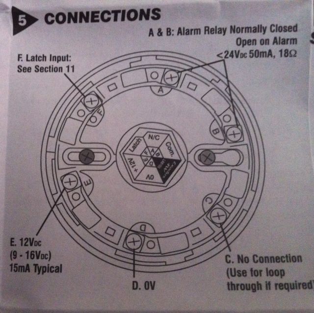
I've also purchased a pair of Texecom Exodus 12v Optical & heat multisensors (OH/4W). I'm guessing (again!) that I connect each one to a separate zone on the panel, but struggling a little on the connection to the detector itself. I'm considering wiring 12v and 0 via red and black again, then (for example) green and blue to A and B relay. The other option (and extra wire) is for latch input of which I know little about at the moment - is it preferable to use the latch option?
Of course, once I've wired up correctly, I'll still have to go through the programming route, but I can cross that bridge when I get to it. Is it essential to link up (via Wintex?) to a computer, or is that for advanced fault finding et al? I'd also consider connecting to a GSM dialler/controller in the future - worth placing a CAT cable in there for the modem (I'm wiring the house up with CAT6 anyway)?
Many thanks - apologies if this is a little long/exhausting!
I've just purchased a Texecom Premier 24 burglar alarm after a good trawl through these boards and on the recommendation of a sparky mate (who unfortunately lives 60 odd miles away...and I've picked his brains far too much of late!).
This will be the first alarm we, as a family, have owned during the past 15 years (we moved into this current house just over a year ago - it had an alarm installed, but was faulty and at least a couple of decades old).
I unpacked this at the weekend and had a good look at the guides and components. Bit daunted if I'm honest, but after a fair bit of homework, I feel a little better about installing it now (I've actually sunk the remote keypad into the brick wall and have started setting the cable runs in (easier as the ceilings are currently down anyway) albeit I still have a few queries!
If any of the following looks as if I've fallen off the path a little, I'd be most grateful if somebody can provide a little advice and guidance:
Ok - typical 1940's semi-detached property. Hallway, kitchen (with back door) and two reception rooms. I plan to place a door contact only in the hallway (although there is also a window in there, it's a non opening one).
I'll place a PIR in the kitchen, one in the living room and one in the dining room (although I could replace the PIR in the kitchen with a door contact...or both?)
The remote keypad is in the hallway, as is the control panel, although that will be behind/in a cloak cupboard. The control panel will be underneath the consumer unit (I literally have nowhere else to place it) so will take it directly from a 3amp MCB via 1 or 1.5mm T&E (nothing else on the circuit). I did intend to place a 3amp unswitched FCU on that circuit, but can't really see any need to now - feel free to disagree.
Wiring - I'm probably going to go down the dual end of line route after reading some of the comments on these threads (seems to be more secure). Fortunately, it seems that the PIR's I have already have the 4K7 and a 2K2 'resistors' built in - I'd just have to move them to the correct position and slot in.
I'll probably go along with red and black for power and choose a colour scheme for alarm and tamper.

The bellbox is a little interesting:
I'm assuming that the end of line method can't be used here? I need 5 wires (2x power, 1 tamper, 1 alarm and one for Strb). Hence, I can't use twisted pairs for alarm and tamper here?

Also, that diagram shows the route for AUX/Fault, but on the actual bellbox there is no connector for this (see pic) - perhaps used on different models?

On the actual panel for the bellbox connections, there is a wire already in the 12v port (I assume for the control panel speaker?) - would I merely place my other power (red) wire alongside this from the bellbox?

So far so good?
I'm also a little unsure which cables go into the zone inputs as there are only two per zone [ZONE 1] [ZONE 2] etc. From a a PIR would I fit one pair of twisted wires (DEOL method) into the left (tamper) and the others (alarm) into the right - and then power (red and black) 12v and 0 into both the left and right (no idea which way round)? I read a post on this forum mentioning a 'COM' connection, but I can't locate that anywhere on the panel?
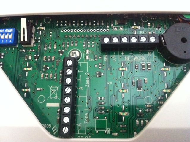
The keypad seems fairly straight forward (linking + - T & R to the corresponding ports on the panel). There is also a Zone 1 and Zone 2 (four ports each split into 2 Alarm and 2 Tamper connections). Not quite sure what these are yet - linking to another keypad? If that's the case, I might drop another 6 core cable in there and send it to our bedroom, just in case we decide on another keypad in the bedroom - sound ok?!

I've actually got the manual online, so I'll have a good read of that later this evening, but I just wanted to see if I'm heading in the right direction.
I've also purchased a pair of Texecom Exodus 12v Optical & heat multisensors (OH/4W). I'm guessing (again!) that I connect each one to a separate zone on the panel, but struggling a little on the connection to the detector itself. I'm considering wiring 12v and 0 via red and black again, then (for example) green and blue to A and B relay. The other option (and extra wire) is for latch input of which I know little about at the moment - is it preferable to use the latch option?


Of course, once I've wired up correctly, I'll still have to go through the programming route, but I can cross that bridge when I get to it. Is it essential to link up (via Wintex?) to a computer, or is that for advanced fault finding et al? I'd also consider connecting to a GSM dialler/controller in the future - worth placing a CAT cable in there for the modem (I'm wiring the house up with CAT6 anyway)?
Many thanks - apologies if this is a little long/exhausting!