Wireless room thermostat wiring

Joined
18 Dec 2012
Messages
10
Reaction score
0
Location
Sussex
Country
United Kingdom
Hi All,

I am trying to figure out the correct wiring for a Horstmann wireless thermostat that I have been too chicken to attempt for over a year now!

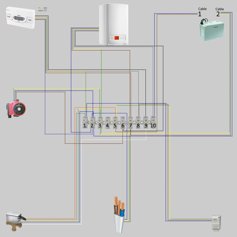
I have mapped the wiring in my junction box and attach a wiring diagram. Forgive the schoolboy approach with graphics, I have no knowledge of how to correctly create an electrical wiring diagram.


I also took the front off the control unit (Drayton LP722) and noted the connections as Neutral and Live in N & L as expected, Green/Yellow in 1 (HW Off), Grey in 3 (HW On) and Black in 4 (CH On). These are indicated on the diagram alongside the control unit picture.

The wireless thermostat receiver has L, N, SL on and SL Off. It suggests in the installation guide that SL off is not normally used. So, working from the diagram, I assume I need to attach Live and Neutral between the receiver and connector block at 7 and 2 respectively.

Where then should I connect the SL on? If using three core and earth with yellow for example, does the current black wire from the LP722 (CH on) become obsolete, with the new thermostat controlling it instead via the yellow? Or does the current black remain in place and get joined by the SL on from the thermostat? Confused obviously!

Many thanks for any help.
 
Sponsored Links
Looking at the drawing I think the next stop should be a sparky.
 
That diagram is too crowded and small I'm afraid. Next time omit the N and E wires for clarity.

So you don't have a room stat at all at the minute?

Mount the wireless receiver next to the programmer if you can.

Take the L-N-E from it into the receiver.

The CH-ON terminal of the programmer should then be connected to the COMMON terminal of the receiver.

The ON terminal on the receiver should then be connected to the spare wire you've just removed from the CH-ON wire in the programmer (this feeds the white wire of the Mid-pos valve.

Are you sure your wireless stat isn't a programmer too?
 
Sponsored Links
The 2 wires in 9 are the switching pair (COM-ON) but the rest don't look right.

5 is definitely wrong.

Perhaps some information, make/models etc.
 
Perhaps some information, make/models etc.

Glowworm Ultracom 24hxi condensing boiler in airing cupboard with HW cylinder
Drayton LP722 control unit
Honeywell 3 way MV
Honeywell cylinder thermostat
 
So it should look like this.

It looks as though the pump is wired back to the boiler in you sketch which is ok.

The wires in terminals 4-5 are your 9.
 
Mount the wireless receiver next to the programmer if you can.

Take the L-N-E from it into the receiver.

The CH-ON terminal of the programmer should then be connected to the COMMON terminal of the receiver.

The ON terminal on the receiver should then be connected to the spare wire you've just removed from the CH-ON wire in the programmer (this feeds the white wire of the Mid-pos valve.

Are you sure your wireless stat isn't a programmer too?

Hi Andy...thanks for the info. Can I just ask a question please? I include a link to the thermostats installation guide.

Installation guide

If you look at page 9 it shows wiring for 230v and volt free applications. I have no idea if I can use the volt free or not, the LP722 says it has volt free contacts but I am not clear what that really means and whether that translates to being able to use the volt free example or not!

So, If using the 230 volt application, I would take the N & L feed from the programmer as you say and also disconnect the CH On from within the programmer and connect directly to the SL (On) connector in the receiver.

Am I right in thinking that the receiver would then have a permanent live from the programmer and as such "The CH-ON terminal of the programmer should then be connected to the COMMON terminal of the receiver. " would then be unnecessary? This would need to be done in volt free application though.

Hope that makes sense, just wanted to check my own understanding, hope it doesn't read as though I am questioning your knowledge!

Thanks again.
 
The advice in my first post is based on it being a room stat only, and not a programmable stat. So forget the reference to "common"

230v and volt free is just the switch. It'll still need 230v to work so you can disregard the reference to "volt free" because you have 230v.
 
disconnect the CH On from within the programmer and connect directly to the SL (On) connector in the receiver.

No. SL on is the feed to the white wire in the Mid-Pos valve. This is the wire that's currently connected to CH-ON in your programmer.

If you mount it next to the programmer it's a simple job.

Permanent LNE are straight forward. Now remove the wire from CH-ON in your programmer and connect it to "heat-on (SL-on) in the reciever.
 
Permanent LNE are straight forward. Now remove the wire from CH-ON in your programmer and connect it to "heat-on (SL-on) in the receiver.
That's confusing! There are two wires on terminal 9: one from the programmer; the other (white) from the motorized valve.

A better way is as follows:

Connect receiver to L , N and E as in the 230V diagram (leave link in place).
Disconnect the white wire from 9 and connect it to 4.
Connect a wire from receiver SL ON to terminal 4.

The CH side of the original programmer has now been bypassed.
 
Just to check for peace of mind, there is no earth connector on the thermostat receiver, just SL off, SL on, L and N, and a second L connected via the jump wire.

I'm not missing something important with earthing am I?
 

DIYnot Local

Staff member

If you need to find a tradesperson to get your job done, please try our local search below, or if you are doing it yourself you can find suppliers local to you.

Select the supplier or trade you require, enter your location to begin your search.


Are you a trade or supplier? You can create your listing free at DIYnot Local

 
Sponsored Links
Back
Top