
You are using an out of date browser. It may not display this or other websites correctly.
You should upgrade or use an alternative browser.
You should upgrade or use an alternative browser.
Bathroom Extractor with timer & humidstat wiring
- Thread starter chamfer
- Start date
Sponsored Links
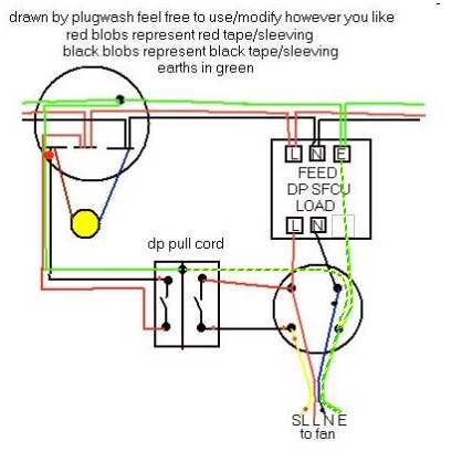
So the manufacturer advised a double pole switch? I don't think plugwash's diagram was quite what they had in mind. Nevertheless, I don't see a double pole switch on their diagram either...
Off hand, I can't see anything wrong with plugwash's design, other than he needs to learn that the if you press the shift key while drawing lines in Paint, then it draws them straight for you.
JB needs to be either MF or accessible, of course.
Off hand, I can't see anything wrong with plugwash's design, other than he needs to learn that the if you press the shift key while drawing lines in Paint, then it draws them straight for you.
JB needs to be either MF or accessible, of course.
I don't think that plugwash's diagram had anything to do with the manufacturer wanting a double pole switch (they're more likely have called for a '3-pole isolator', anyway) - I think the DP switch is all about getting both the L and S/L to the fan protected by a 3A FCU (which the manufacturer probably also called for!) without having to fiddle with (insert the FCU in) the supply feed to the light.So the manufacturer advised a double pole switch? I don't think plugwash's diagram was quite what they had in mind.
Kind Regards, John
Sponsored Links
It's a touchy subject lol and difficult to agree on.
If the manufacture is asking for a 3a fuse to be fitted go with the diagram above.
If they are only asking for a double pole switch then fit a triple pole switch to the wires to the fan.
If the manufacture is asking for a 3a fuse to be fitted go with the diagram above.
If they are only asking for a double pole switch then fit a triple pole switch to the wires to the fan.
As as already been said, that's a bit odd since their diagram includes only a single-pole switch! 'Double-pole switch' usually implies switching of both live/line and neutral. However, with a timer fan there are two lives (L and S/L) as well as neutral, so manufacturers usually specify a 3-pole switch/isolator.A double pole switch is what they have asked for, do you know a better way other than plugwash drawing?
Whatever, plugwash's diagram would satisfy the manufacturer's requirement, since the switched FCU would qualify as the 'double pole switch' they ask for. the other DP switch (labelled 'DP pull cord' in plugwas's diagram) being the light (and fan initiating) switch.
Kind Regards, John
The single pole switch in the diagram is the light switch and they haven't shown a double pole switch !!!
Quite so:The single pole switch in the diagram is the light switch and they haven't shown a double pole switch !!!
... and, unless one converts the light switch to a DP one (per plugwash) one would need a 3-pole switch/isolator to achieve 'all-pole' isolation of the fan.As as already been said, that's a bit odd since their diagram includes only a single-pole switch!
Kind Regards, John
A double pole switch is what they have asked for, do you know a better way other than plugwash drawing?
It might be being a bit pedantic but it seems to me that when they asked for a double pole switch, using one pole to switch the fan and one to switch the light wasn't quite what they had in mind. It'd be a bit like only wiring up one pole and then saying "A DP switch was what you asked for a and a DP switch you received". It's hard to know what exactly they had in mind as their diagram didn't actually include a DP switch but the only sensible arrangement of DP isolation would be to isolate line and switched line. As this is provided by a single pole switch and a JB, while it does provide isolation it doesn't really meet the manufactures instructions. On the other hand, the SFCU does provide dual pole isolation and one might argue, given the downstream switch, in effect three-pole but then does SFCU == switch? Perhaps it would have been better for the manufacturer to state "means to isolate live conductors". *
TL;DR: I can't see anything wrong with plugwash's diagram.
* Please let's not get started on the do we need to isolate the neutral conductor debate.
I doubt that's what they meant - I've never seen a fan's MIs suggest such an arrangement. I wonder if the OP is reading the right MI, or the right part of the MI, or perhaps misunderstanding something? When they mention isolation, IME the MIs always call for DP isolation (L & N) of non-timer fans and 3-pole isolation (L, S/L and N) of timer fans - in both cases, they mean 'all-pole isolation' (including neutral).It's hard to know what exactly they had in mind as their diagram didn't actually include a DP switch but the only sensible arrangement of DP isolation would be to isolate line and switched line.
I don't think you can get away from it - as above, I've never seen MIs for a fan which specify an isolator without requiring it to isolate N as well as L(s) (2-pole for non-timer, 3-pole for timer models).* Please let's not get started on the do we need to isolate the neutral conductor debate.
Kind Regards, John

- Joined
- 2 Mar 2014
- Messages
- 96
- Reaction score
- 18
- Country

Fig 8 is showing the connection to the light not the DP or any other means of total isolation. I think for isolation you need to be looking at one of the other diagrams 5, 6, or 7. But if the model is the CRZ then like others have said I would be looking to put in 3 pole isolation.
Edit: Just looked at the manual on TLC site only shows DP isolation on 1 model???????
Edit: Just looked at the manual on TLC site only shows DP isolation on 1 model???????
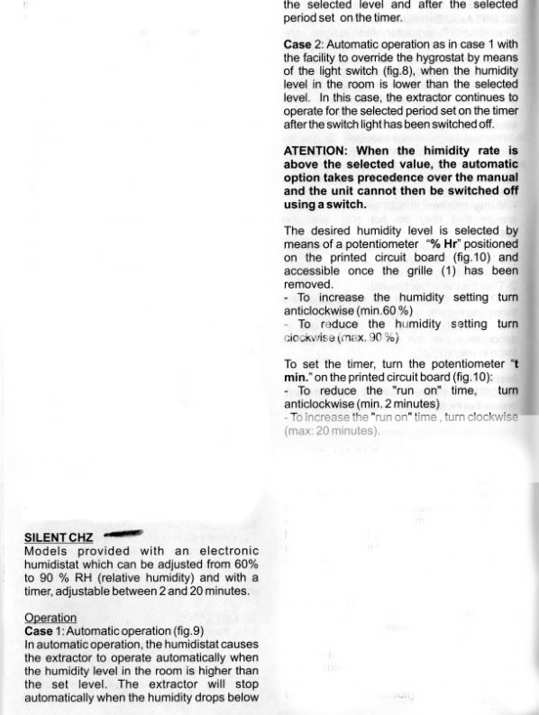
Hmmmm - it looks as if they have copies the bit about a "double pole switch with 3mm contact separation" from some manufacturer's instructions for a non-timer fan, and have not noticed that manufacturer's of fans with timers almost invariable call for a 3-pole switch/isolator with 3mm contact separation! What make (and nationality) is this fan?pic of instruction
Kind Regards, John
- Joined
- 11 Jan 2012
- Messages
- 107
- Reaction score
- 1
- Country
The Company
Soler & Palau Ltd is the UK subsidiary of the Soler & Palau group of companies. Established in 1985 Soler & Palau Ltd have been supplying a wide range of specialist fan and air moving products to a diverse national and international OEM client base.
Soler & Palau (UK) Ltd's operations are based on the prestigious Ransomes Europark Business Estate in Ipswich, Suffolk. From this geographically strategic location products are imported from the various European and Pan Pacific Soler & Palau group manufacturing facilities and stocked at the company's extensive warehouse premises in Ipswich. The stocking of this comprehensive range of products permits the overnight delivery of many popular model sizes to anywhere in the mainland UK.
DIYnot Local
Staff member
If you need to find a tradesperson to get your job done, please try our local search below, or if you are doing it yourself you can find suppliers local to you.
Select the supplier or trade you require, enter your location to begin your search.
Please select a service and enter a location to continue...
Are you a trade or supplier? You can create your listing free at DIYnot Local
Sponsored Links
Similar threads
- Replies
- 4
- Views
- 2K
- Replies
- 19
- Views
- 2K
- Replies
- 51
- Views
- 6K