Ideal C28 boiler not igniting

Joined
31 Mar 2012
Messages
7
Reaction score
0
Location
West Glamorgan
Country
United Kingdom
Hi guys, my boiler is failing to fire up in either CH or DHW mode.

I have carried out the fault finding as per the manual and after a short period the LEDs indicate a lack of burner ignition (no ignition signal from the full sequence ignition device). The boiler itself tries to fire up, but then there is a click before the boiler attempts to fire again. This sequence is repeated until CH or DHW is turned off. Is this a common fault and if so what are the typical causes?

I carried out some initial diagnostics, and there is 240V at the fan connector, which cycles with the boiler trying to fire. I carried out continuity tests of the safety thermostat and air pressure switch which showed no faults.

I then measured the supply to the gas valve but didn’t get 240V across the valve terminals. I then measured at the PCB connector with similar results.

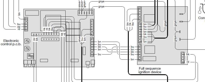
There is an interconnector between the two PCBs, consisting of two blue cables, two brown and a black in the centre. I measured across the first blue brown pair and had 240V, but when I tried to measure across the second blue brown (top pair on the ignition PCB), there was a spark and the boiler went dead.

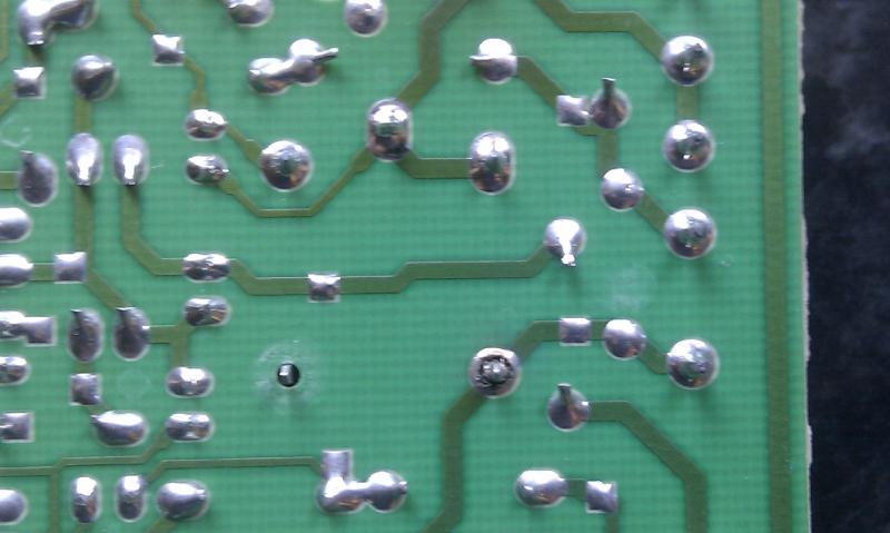
I removed the fuse from the control PCB and found it blown. Is there a common fault which would cause a short across this connector?
So at the moment I need to replace the control PCB fuse before continuing, but if I could bet any advice or pointers I would be most grateful.

Many thanks,

Chris
 
Sponsored Links
Ignition module if there is one on that boiler.
Otherwise sounds like PCB a frequent and expensive problem
on Ideal boilers.
 
Sponsored Links
This boiler is made by Biasi.

The OP has already opened the combustion chamber which is not recommended for a DIYer.

The obvious advice is to call a competent gas reg boiler engineer.

Tony
 
No I've not opened the combustion chamber, I carried out the continuity checks at the PCB terminals.

I've replaced the fuse this morning. I get 6V when measuring the voltage across the modulation gas valve coil. The book says this should be 16V and if not to change the PCB.

I'm just looking for some pointers so I can confirm if its a PCB fault or not. I don't suspect its a fault with the gas side.

Cheers
 
The voltage applied to the mod coil varies from 6-18v depending on what power setting the boiler feels is required.

I still dont see how you could test NO and NC on the APS at the PCB.

What were you doing when there was this spark?

Tony
 
Cheers Tony,

I just carried out continuity checks of the NC & NO on the PCB connector.

I was measuring the voltage across the top brown and blue wires of the PCB inter connector. I'm not getting any voltage across this pair.


I've also noticed that the click is coming from the power relay on the sequence PCB. I removed this PCB and there appears to be no significant scorching and the solder joints seem good apart from 1 on the power relay. There also appears to be a pad missing from pin 4...


I've also measured the resistances of the modulating gas valve coils and they all match the values given in the Biasi manual I've just downloaded.

It also says in the Biasi manual that the control PCB supplies the sequence PCB, which leads to me believe the control PCB is at fault...

Chris

I've carried out all the voltage checks in the Biasi manual, and the only voltages I haven't got are both of the 230V supplies to the modulating gas valve. I still can't find anywhere if there should be a voltage across both blue brown cables on the PCB inter connector cable.

So as it stands I have the lack of burner ignition fault according to the LEDs and I'm not getting the required voltage to operate the modulating gas valve.

I've seen the sequence PCB on Allspares for £50. I'm half tempted to order 1 and see what happens.
 
I've also noticed that the click is coming from the power relay on the sequence PCB. I removed this PCB and there appears to be no significant scorching and the solder joints seem good apart from 1 on the power relay. There also appears to be a pad missing from pin 4...


theres your problem then, theres a dry joint on the one to the right also.

i would say resolder them but as you say, theres a pad missing.
 
Cheers Paul,

Yeah the missing pad is strange as that relay leg looks like its never been soldered and the boiler has worked fine for 8 years!!!

I'm going to reflow that joint and see what happens...

Chris
 
Cheers Paul,

Yeah the missing pad is strange as that relay leg looks like its never been soldered and the boiler has worked fine for 8 years!!!

I'm going to reflow that joint and see what happens...

Chris

good call, thats what id do.
 
AH-HA!!!

Quick trip to Maplin's to get a cheap soldering iron and some solder wick...

Cleaned and reflowed that dry joint, job done!!

Cheers for the pointers guys.

Chris
 
So it it working then?

That missing pad is for a pin which is not used. But its soldered to add mechanical stability to the relay.

I am not sure exactly which one it is but probably the fan relay.

Tony
 
Yeah boiler working fine on both central heating and hot water. Well chuffed...

:D :LOL: :D

It is strange that there is no pad on that pin, its probably a manufacturing defect which has not been picked up or let through as board was functioning correctly and not worth the rework just for stability.

Thanks again for the advice guys

Chris
 

DIYnot Local

Staff member

If you need to find a tradesperson to get your job done, please try our local search below, or if you are doing it yourself you can find suppliers local to you.

Select the supplier or trade you require, enter your location to begin your search.


Are you a trade or supplier? You can create your listing free at DIYnot Local

 
Sponsored Links
Back
Top