
You are using an out of date browser. It may not display this or other websites correctly.
You should upgrade or use an alternative browser.
You should upgrade or use an alternative browser.
2 pir 1 cable (can you loop)
- Thread starter Needy
- Start date

Sponsored Links
Y
yaleguy3
Yes you can. You could have more than 2 pirs on a single zone wire. The problem starts when you want your panel to indicate which zone started the alarm and you have more than one room on the same zone so obviously you would not be able to tell if you were getting false alarms which pir was causing it. Bit like when the xmas tree lights don't work and you end up checking every bulb before you find the faulty one (usually the fiftieth one).
You would have to wire them in series for the tamper and sensor and parallel for the power
scroll down in this webpage to see a diagram.
http://www.letsfixit.co.uk/html/burglar_alarms.html
You would have to wire them in series for the tamper and sensor and parallel for the power
scroll down in this webpage to see a diagram.
http://www.letsfixit.co.uk/html/burglar_alarms.html
.. or as this is a DiY alarm and as it has been assumed you are using a 6 core cable do it the following way.You would have to wire them in series for the tamper and sensor and parallel for the power
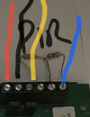
Red / black 12v to both detectors
Blue / yellow to the first PIR alarm contacts
Green / white to the second PIR alarm contacts
You can then wire the detectors to their own individual circuits back at the control panel, (and forget about the Xmas lights).
Don't forget to 'loop out' the A/T half of these two circuits at the control panel, but as we don't know what panel you have, if it has a universal tamper circuit just forget about them.
OK, you've not got anti tamper at either detector, but in your situation is it really necessary?
If you only have a 4 Core cable it's possible to do the same thing but in a different way, not right as the above isn't, but it can be done, I'd have to write an essay!
Any chance you could write thats essay as I have a 4 core cable to 2 sensors that are back to back to each other in 2 rooms and I can’t get the buggers to work
im on a Eaton Ion40H and the keypad doesn’t like it
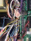
for some reason I feel it’s the power source as when I connect that to the Aux it throws out the wifi and the 12v Aux
so something about it, it doesn’t like.
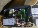
I have 2 banks of 12v OV and there chocka with wires
can you get 12V off a different spot?
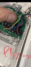
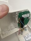
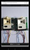
pics attached
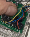
note last 2 pics are how they were wired originally with No tamper and yellow blue opposite way around at N/C using no resistors……..
the other pic of PIR is his the others are wired
thank you
im on a Eaton Ion40H and the keypad doesn’t like it
for some reason I feel it’s the power source as when I connect that to the Aux it throws out the wifi and the 12v Aux
so something about it, it doesn’t like.
I have 2 banks of 12v OV and there chocka with wires
can you get 12V off a different spot?
pics attached
note last 2 pics are how they were wired originally with No tamper and yellow blue opposite way around at N/C using no resistors……..
the other pic of PIR is his the others are wired
thank you
Attachments
-
 A087E719-D3E0-4461-8942-8802EAB7F9FD.jpeg304.1 KB · Views: 90
 -
 D807753B-DD94-46AB-8043-6014EDA18AF3.jpeg462.5 KB · Views: 96
 -
 8C4D03B6-1FA2-439D-B4E1-15FC8DCDBFCF.jpeg145.8 KB · Views: 90
 -
 9A9319E8-5605-4850-A843-7ABD7E7C3CCA.jpeg736.5 KB · Views: 120
 -
 364123C3-2652-4055-9165-DC943B03D748.jpeg180.8 KB · Views: 88
 -
 08FFA1F5-87D3-44BE-8537-39F0718F3462.jpeg145.7 KB · Views: 96
 -
 C444173C-2D23-4714-B539-AAA044CE3A7B.jpeg172.9 KB · Views: 91
Sponsored Links
Thanks you
Trouble is I only have 4 wires for these two PIRs the rest are 6 wires but only using 4 as per the first photo with resistors.
that’s what’s confusing and I can’t get behind them and look as they are both been boxed into a bookcase and kitchen cupboards.
so no idea how they are wired up behind…
first phone is now the others are wired
second and third photo is how they were wired before.
then at label same as others in 4th phone but tht then seems to throw out the Power as it reads 12v Aux fault at panel
very frustrating, can I take power from elsewhere?
Attachments
-
 0B9F5EA6-B860-4B17-AE80-09A91EBD3197.jpeg104.2 KB · Views: 92
 -
 A69ED21C-39D6-427C-A09B-04008A060C2B.jpeg145.7 KB · Views: 64
 -
 BDECE50F-929E-4163-A6DE-40FC98C02855.jpeg180.8 KB · Views: 74
 -
 9F2B9787-97D2-43C8-8929-189FDE8EEC11.jpeg243.3 KB · Views: 135
 -
 6E72723D-E4C1-4D16-B085-0E93FA1E4DBB.jpeg420.7 KB · Views: 71

That’s been rectified now and all sorted
it’s juts these 2 PIR on the same cable I need to sort and I’m done
so at…..
PIR 1 - I’ve wired as per the first photo
PIR 2 - I’ve wired as per the second photo
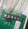
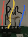
and at panel I have wired as this
with no resistors
and only option at keypad I have is a 2 wire with resisters
1-k/1k
2/4
4/7
so I’m gonna have to use resisters right?
like photo four but that didn’t work the first time but was coming through the tamper p
thoughts please gentlemen
it’s juts these 2 PIR on the same cable I need to sort and I’m done
so at…..
PIR 1 - I’ve wired as per the first photo
PIR 2 - I’ve wired as per the second photo
and at panel I have wired as this
with no resistors
and only option at keypad I have is a 2 wire with resisters
1-k/1k
2/4
4/7
so I’m gonna have to use resisters right?
like photo four but that didn’t work the first time but was coming through the tamper p
thoughts please gentlemen
Attachments


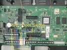
Do both detector cables go back to control panel?
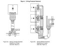
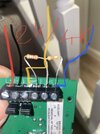
Wire 1st pir as standard EOL
2nd pir put link from tamper terminal to alarm terminal, put 4.7k resistor across zone.
In control panel join both yellow wires together with connector block,then put blue wires in zone connection on pcb
As picture.
Hope this has made it clearer for you.
Wire 1st pir as standard EOL
2nd pir put link from tamper terminal to alarm terminal, put 4.7k resistor across zone.
In control panel join both yellow wires together with connector block,then put blue wires in zone connection on pcb
As picture.
Hope this has made it clearer for you.
Attachments
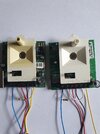
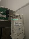
No they don’t they spured off the existing cables here’s the original wiring set up
PIR 1 first pic
PIR 2 Second pic
this is how I wired the other PIRs - third pic
PIR 1 first pic
PIR 2 Second pic
this is how I wired the other PIRs - third pic
Attachments


DIYnot Local
Staff member
If you need to find a tradesperson to get your job done, please try our local search below, or if you are doing it yourself you can find suppliers local to you.
Select the supplier or trade you require, enter your location to begin your search.
Please select a service and enter a location to continue...
Are you a trade or supplier? You can create your listing free at DIYnot Local
Sponsored Links
Similar threads
- Replies
- 2
- Views
- 637
- Replies
- 5
- Views
- 739
- Replies
- 4
- Views
- 5K