I missed that day in collage power factor!

Joined
27 Jan 2008
Messages
23,663
Reaction score
2,666
Location
Llanfair Caereinion, Nr Welshpool
Country
United Kingdom
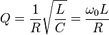
OK seems daft but I never paid attention to power factor correction. Silly I know but I can work out resonant frequency and ƒ = 1/2π√LC etcetera is no stranger to me. I know the principle of power factor correction and have been involved in fitting automatic units but when I tried reading up on the subject I got totally confused.

I remember from doing RAE working with Q and have that in the back of my mind of how the higher the Q the tighter the frequency but reading the accounts on power factor correction it seems to have another use of Q.

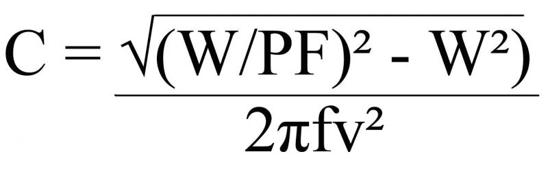
On reading a USA account with 60 Hz and 120 volt it explains how to work it out but my results are 1000000 times out instead of F! I seem to get μF.

So general principle I understand but when it comes to working out what capacitor to put across a motor supply to bring it back to unity.

XL = XC = X or XC – XL = X that I understand but a motor does not have XL marked on it so how is it measured? I can measure amps and volts so easy to get VA but how do I measure watts?

I know Z = √X² + R² but to get X? I need both XC and XL and this has just stumped me.
 
Sponsored Links
There are three 'types' of power.

Q is the reactive power, its measured in VAr and is the magnetic energy exchanged by an AC circuit. It does no 'work' but merely moves backwards and forwards between the supply and the load.

W is the real power, its measured in Watts and is the 'work done'.

S is the apparent power, its measured in VA and is the product of Volts X Amps. Its the only one that can be measured directly.

Q & W are considered to be at right angles to each other (W is horizontal & Q is vertical) hence S is the hypotenuse of that power triangle. The lower angle, between W & S is called the power angle, the cosine of which is the power factor.

W is also calculated as the voltage * component of the current that is in-phase which the voltage ie V * I * sin (power angle).
 
The bottom line is you can't measure real power with normal multimeters/clamp meters. You can measure the RMS voltage and RMS current but you can't measure the phase relationship between them.
 
Q is the reactive power, its measured in VAr and is the magnetic energy exchanged by an AC circuit. It does no 'work' but merely moves backwards and forwards between the supply and the load.
Now I think this may be the problem in my understanding as I thought Q was the band width where the capacitance and inductive components will be resonate. Wikipedia here seems to confirm what I thought Q was

Since they are so similar I have thought they were the same unit
4218f791bdd88097ab2318478914d431.png
I have always used the formula
199777b120723831bf53a9cd6a762185.png
for radio work but with a radio we know the inductance size and capacitor size they are written on the outside of the device from my understanding it is the resistor size which determines the value for Q there is always some resistance in a coil of wire.

But that's radio although same formulas may be used for power factor measuring is it would seem the problem.

I have a plug in meter which records power used and has a read out of watts, volts, amps, kWh and power factor I normally use it to test fridge/freezers to see how much power they are using and identify when there is a thermal insulation break down. How it measures power factor not a clue but tungsten lamp is 1 and fridge/freezer 0.9(something) so it would seem to work.

So two questions
1) If I used that meter with a florescent lamp and it showed 0.75 how would I work out from that figure what capacitor to place across the supply?
2) How does the meter work out the power factor?

I know the principle but not how to use it.
 
Sponsored Links
The 'Q factor' is a different beast altogether.

The Q we talk about in power engineering is the reactive power, its unit being the VAr. Whereas the Q factor is dimensionless?

Your plug-in meter probably calculates Q by measuring the time difference between the zero crossing of the voltage waveform & the zero crossing of the current waveform. From this you can calculate the electrical angle between the two & hence calculate W & Q from the measured S.

To calculate the required capacitor for the fluorescent lamp you would need to know the reactive power used when the lamp is operating. Using this, you would work backwards to calculate the value of capacitance which would use the same magnitude of reactive power. Since, with an inductor, the current lags the voltage & with a capacitor it leads, when you connect your capacitor into the circuit the reactive components of the current will cancel.
 
In tuned circuits the Q value is a value of "goodness", in simple terms it is roughly the ratio between the power that gets through the filter to the power that does not get through the filter. ( at that is how is was told to me in simple terms by the radio experts in the company ).
 
If for an example I take a florescent lamp where the correction capacitor is missing. From the plug in meter I have watts and power factor it does not show VA so problem is I need the VA before I can start so this would seem to be how!

Power factor = Watts/VA
So if watts = 58 and power factor was 0.75 then VA = Watts/PF = 77.3VA
Reactive power = √VA² - W² = 51.1
X = E²/Q = 230²/51.1 = 1039
C = 1/2πfXc = 3μF

Is that how it should be done? The result for C was times by 1000000 to get to μF. It seems a reasonable result.

Is what is seems to cancel down to to find the capacitor from power factor correction, Watts, Volts, and frequency.
 
In tuned circuits the Q value is a value of "goodness", in simple terms it is roughly the ratio between the power that gets through the filter to the power that does not get through the filter. ( at that is how is was told to me in simple terms by the radio experts in the company ).
Indeed. As Adrian has said, the 'Q factor' of radio and electronic engineers is a totally different animal from the electrical engineer's 'Q' which is reactive power.

As you say, in terms of tuned circuits, the 'Q factor' is a measure of 'goodness'. Whilst what you say above is true, and would be relevant to tuned circuits in high power RF applications, the main practical relevance is not to do with 'lost power' but, rather, is in relation to the 'bandwidth' (the range of frequencies over which the impedance of a series tuned circuit approaches zero, or the impedance of a parallel tuned circuit approaches infinity).

As eric has illustrated, mathematically, Q factor is nothing more than the reactance (of either capacitor or inductor - which will be equal at the resonant frequency) divided by the resistance in the circuit (hence, as Adrian said, dimensionless). A 'perfect' tuned circuit (only capacitance and inductance, but zero resistance) will therefore have an infinite 'Q factor', and thus a minimal 'bandwidth'.

Kind Regards, John
 
If for an example I take a florescent lamp where the correction capacitor is missing. From the plug in meter I have watts and power factor it does not show VA so problem is I need the VA before I can start so this would seem to be how!

Power factor = Watts/VA
So if watts = 58 and power factor was 0.75 then VA = Watts/PF = 77.3VA
Reactive power = √VA² - W² = 51.1
X = E²/Q = 230²/51.1 = 1039
C = 1/2πfXc = 3μF

Is that how it should be done? The result for C was times by 1000000 to get to μF. It seems a reasonable result.

Is what is seems to cancel down to to find the capacitor from power factor correction, Watts, Volts, and frequency.

Yes, that's the idea. I haven't checked the math but 3uF is about the right value for a small florrie.

The idea is to balance the reactive current demanded by the inductor to that created by the capacitor. That way, the two reactive elements exchange the reactive current & the supply only provides the current needed to create the Watts.

This is only true for a 'stiff' supply. Its important not to attempt PFC when using a generator as a supply - its all to easy to create a resonant system and start to lift up the supply voltage (as happened at TVS when I was there some years back.)

On a three phase supply, a quick way of getting a VAr meter is to connect a Wattmeter in such a way that the voltage sensing comes line-line from the other two phases instead of the same phase as the load. A little vector maths shows that the line-line voltage from the Y-B is 90 deg shifted from the R-N voltage. Hence multiplying the Y-B voltage by the current in R phase will give the reactive power in R.
 
Power factor = Watts/VA
So if watts = 58 and power factor was 0.75 then VA = Watts/PF = 77.3VA
Reactive power = √VA² - W² = 51.1
X = E²/Q = 230²/51.1 = 1039
C = 1/2πfXc = 3μF
Is that how it should be done?
Yes, I think you've got the maths roughly right. I make (230²/51.1) 1035 Ω, rather than your 1039 Ω, but the (rounded) 3μF answer is still correct - and, as Adrian has said, sounds roughly right.

As you have illustrated, all this is about is ascertaining the inductive reactance of the load and then determining the capacitance which would have that same reactance at 50Hz. It can get a bit confusing because of this concept of 'reactive power' - which, of course, is not power at all in terms of physics - in context, it's just a fairly abstract 'means to an end' to enable one to determine the inductive reactance.

Kind Regards, John
 

DIYnot Local

Staff member

If you need to find a tradesperson to get your job done, please try our local search below, or if you are doing it yourself you can find suppliers local to you.

Select the supplier or trade you require, enter your location to begin your search.


Are you a trade or supplier? You can create your listing free at DIYnot Local

 
Sponsored Links
Back
Top