Salus RT500RF Thermostat to Vokera Compact Help Please!

Joined
24 Sep 2014
Messages
7
Reaction score
1
Location
Manchester
Country
United Kingdom
Hi All and thanks for taking time to read my 1st post :)

I have just purchased the RT500RF to connect to my Vokera Compact boiler.
I have received mixed information on how to wire this unit, I'm being told it only needs two wires to the Vokera range?? How true this is I don't know<?>

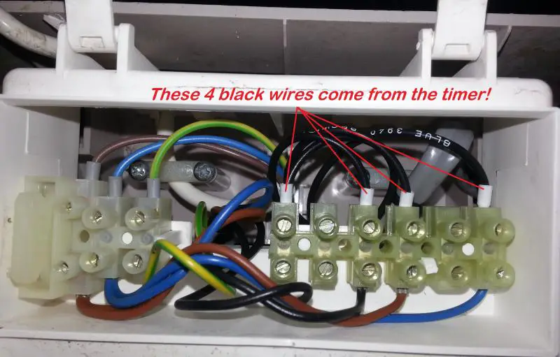
This picture shows the 4 wires coming from the timer switch.

I'm unsure if I fully remove the 4 wires rendering the timer useless or not?


Could someone please help me out as good old British Gas want £199 to fit it, surely it's not that difficult?

Many Thanks in advance for any help offered :)

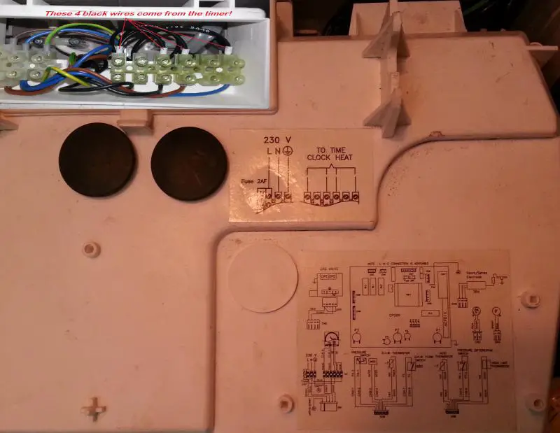
PS. This is the diagram on the top of the control unit, the above picture is under a flap at the top left.

 
Sponsored Links
If you look at the connector block for the timer.

Remove all 4 black wires from the top row.
Connect Salus Live to Brown
Connect Salus Neutral to Blue
Connect Salus COM to any Black
Connect Salus NC to the other Black.

Change dip switch settings on the receiver and the jumper stings on the transmitter to suit (i.e. flick receiver dip switches 1 and 4 and remove transmitter jumpers 1 and 4). This just reduces the chances of interference with any other Salus controllers in your area.

James.
 
Hi James and thanks for the reply mate.

May I just ask (only I was told) that the Vokera Compact only need's two wires connecting between the boiler and the Salus?

Like I said in my previous message, I have received various methods of connecting this device, but yours makes more sense :)

If you look at the connector block for the timer.

Remove all 4 black wires from the top row.
Connect Salus Live to Brown
Connect Salus Neutral to Blue
Connect Salus COM to any Black
Connect Salus NC to the other Black.

Change dip switch settings on the receiver and the jumper stings on the transmitter to suit (i.e. flick receiver dip switches 1 and 4 and remove transmitter jumpers 1 and 4). This just reduces the chances of interference with any other Salus controllers in your area.

James.

Pass, maybe they don't know what they are doing. You need a power supply for the receiver, this way it is also fused from the power supply inside the boiler.

James.
 
Sponsored Links
Cool... Thanks again James :)

I'm going to have a pop at this tomorrow, so just to confirm:

Salus Live to Brown - Straight Forward :)
Salus Neutral to Blue - Straight Forward :)
Salus COM to any Black - So this "can" be either Black ?
Salus NC to the other Black - And this can be the other ?
Do these last two have no specific order as long as it's connected to a black wire?

Sorry, just double checking all before I blow myself up LOL

Hi James and thanks for the reply mate.

May I just ask (only I was told) that the Vokera Compact only need's two wires connecting between the boiler and the Salus?

Like I said in my previous message, I have received various methods of connecting this device, but yours makes more sense :)

If you look at the connector block for the timer.

Remove all 4 black wires from the top row.
Connect Salus Live to Brown
Connect Salus Neutral to Blue
Connect Salus COM to any Black
Connect Salus NC to the other Black.

Change dip switch settings on the receiver and the jumper stings on the transmitter to suit (i.e. flick receiver dip switches 1 and 4 and remove transmitter jumpers 1 and 4). This just reduces the chances of interference with any other Salus controllers in your area.

James.

Pass, maybe they don't know what they are doing. You need a power supply for the receiver, this way it is also fused from the power supply inside the boiler.

James.
:?: :?:

Correct, all that is between COM and NC is a switch basically. I think they could be volt free on the Vokera anyway, I could be wrong.

James.
 
OK Thanks

So should I just connect Salus Live to Brown & Salus Neutral to Blue and see how I get on? or could I blow it doing that?

If it does not work, then connect the blacks?

Mark
 
OK Thanks

So should I just connect Salus Live to Brown & Salus Neutral to Blue and see how I get on? or could I blow it doing that?

If it does not work, then connect the blacks?

Mark

Mark, stop messing about, either take my advice or hire a professional who will basically do what I've suggested.

James.
 
OK Thanks

So should I just connect Salus Live to Brown & Salus Neutral to Blue and see how I get on? or could I blow it doing that?

If it does not work, then connect the blacks?

Mark

Mark, stop messing about, either take my advice or hire a professional who will basically do what I've suggested.

James.

Sorry mate, did not mean to offend, Just that this is my first time doing this, just don't want to toast myself..

Thanks for your help, will follow your instructions tomorrow :)
 
If you connect only the brown and blue you will get a nice power light on the receiver and the thermostat will even connect to it... But it won't switch on the heating. The black wires are the 24v switching wires (one leading into the receiver and one leading out which is connected when the thermostat is turned up high enough) to tell the boiler to actually fire. All 4 need to be connected. Whoever told you it only needs 2 wires was either plain wrong or meant 2 wires from the boiler (blacks) and an additional 2 wires (brown and blue) to power it from the fuse spur directly (overcomplicated when they can all be taken from the boiler).
 
If you connect only the brown and blue you will get a nice power light on the receiver and the thermostat will even connect to it... But it won't switch on the heating. The black wires are the 24v switching wires (one leading into the receiver and one leading out which is connected when the thermostat is turned up high enough) to tell the boiler to actually fire. All 4 need to be connected. Whoever told you it only needs 2 wires was either plain wrong or meant 2 wires from the boiler (blacks) and an additional 2 wires (brown and blue) to power it from the fuse spur directly (overcomplicated when they can all be taken from the boiler).

Ah right, so the black wires are 24v and not volt free. Still makes no difference in the OP's case.

James.
 
I hope you dont think I am being picky but there is no such thing as "volt free" switching, wires have to have voltage to make the boiler fire, the volt free refers to the switches not using the voltage that makes the switch :confused: if you see what I mean.
 
Volt free means the voltage for switching the appliance on is not generated by the roomstat receiver. ;)
 
Thank You all for your help and advice on this topic, I've not had chance to fit it yet due to being called into work, I now plan to have a bash over the weekend :)
 

DIYnot Local

Staff member

If you need to find a tradesperson to get your job done, please try our local search below, or if you are doing it yourself you can find suppliers local to you.

Select the supplier or trade you require, enter your location to begin your search.


Are you a trade or supplier? You can create your listing free at DIYnot Local

 
Sponsored Links
Back
Top