My dangerous and bodged electrics!

Joined
28 Jul 2012
Messages
1,348
Reaction score
55
Location
Surrey
Country
United Kingdom
Not got to much to say here :oops: , other than I stumbled upon these old photos of my old garage while looking for something else on my computer.

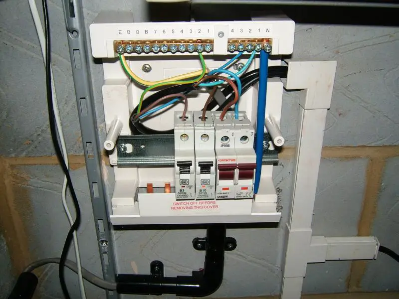
Let's just say back then I did not know what I now know what will become very obvious with the photos and the state of my electrical work back then. Note this work was removed when I moved and no longer exists.

I want to make it very clear, back then I did not know what I did was dangerous and unsafe.

And, yes I am prepared for the telling off and backlash towards me. :cry: :rolleyes:

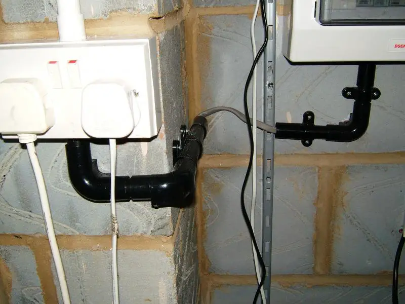
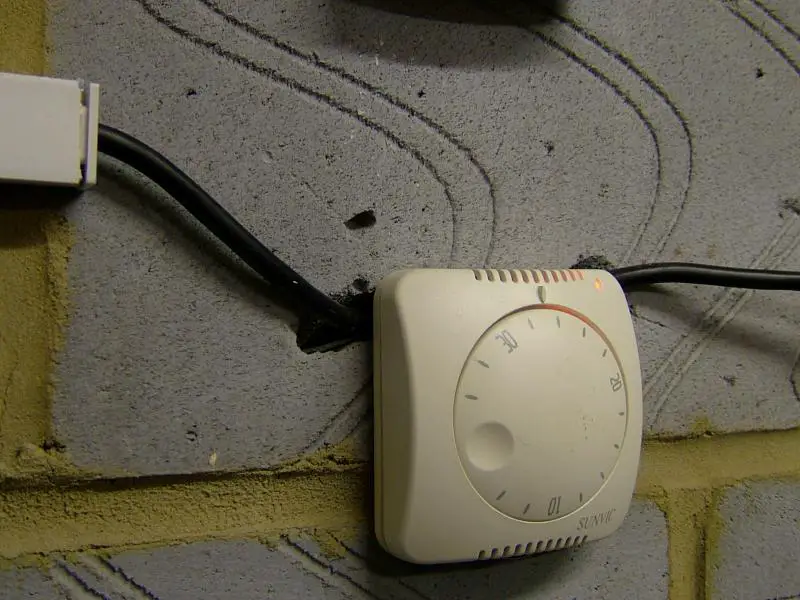
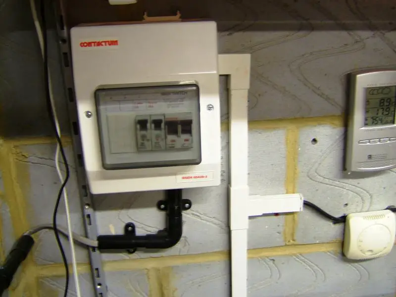
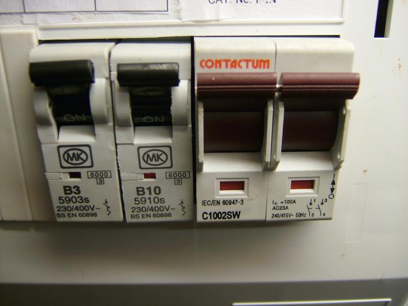
Let the horror of my work begin!


Sponsored Links
WEll, its untidy, and i do not see why a mini consumer unit was needed - a couple of FCUs would have been enough - but dangerous? Why do you think so?
 
As above untidy and not aesthetically pleasing to the eye. But unsafe/dangerous, at a glance does not look.
I see much worse almost everyday. On a DIY disaster at the moment, where the previous occupants, had no idea about loading, cable rating, safe routing, safe terminal connections, external and environment influences.
 
Sponsored Links
WEll, its untidy, and i do not see why a mini consumer unit was needed - a couple of FCUs would have been enough - but dangerous? Why do you think so?
Depends how it all starts off - looks like the CU is supplied from the socket to the left, so where does that originate? Unfused spur from a ring final?

Then there's the lack of cpc in one of the circuits from the CU.
 
I'm not sure there is a CPC missing, it looks to me like there might be one hiding behind the one we can clearly see though the picture is too fuzzy to tell for sure.
 
Depends how it all starts off - looks like the CU is supplied from the socket to the left, so where does that originate? Unfused spur from a ring final?
I'm not so sure about that - it looks to me as if that T&E is supplying the socket to the left (via the B10). The incoming supply (to the main switch) is coming from one of the black flexes.
Then there's the lack of cpc in one of the circuits from the CU.
As has been said, it's not really clear. One can but presume that the conductor (at least, one of the conductors) inside that G/Y sleeving (and, confusingly, connected to the 'E' terminal of the earth bar) is the CPC of the T&E - which, as above appears to be one of the output circuits. The black flex which is presumably the incoming supply (blue and brown go to main switch) has no obviously visible CPC, although one may be hidden, not helped by the fact that, if it exists and is connected to the earth bar, it has not been put into a terminal of its own in the bar (i.e. if it exists it must either be going into the same terminal as the other flex's CPC or hidden inside the G/Y sleeving with the T&E's CPC).

Some clarification from OP would be helpful!

Kind Regards, John
 
I'm not so sure about that - it looks to me as if that T&E is supplying the socket to the left (via the B10).
Not to me.

screenshot_327.jpg


Also can't see a 3rd cpc anywhere.


Some clarification from OP would be helpful!
Note this work was removed when I moved and no longer exists.
:confused:
 
I'm not so sure about that - it looks to me as if that T&E is supplying the socket to the left (via the B10).
Not to me.
I'm not really sure what point the pic is making. My point was that the the brown and blue (presumably L&N!) going to the main switch clearly come from one of the black flexes, and that the brown of the T&E appears to be connected to the B10. That leads me to the conclusion that the T&E (which goes to the socket on the left) must be supplying the socket, the incoming power to the CU coming from somewhere else (via black flex). What am I missing?
Also can't see a 3rd cpc anywhere.
As I said, I agree that one cannot see a CPC coming from what I assume is the incoming supply flex (whose brown and blue go to main switch). However, as I said, it's conceivable that it's hidden, either behind the one from the other flex or possibly within the G/Y sleeving over the (one assumes) T&E's CPC, and connected to one of the two terminals being used.
Some clarification from OP would be helpful!
Note this work was removed when I moved and no longer exists.
:confused:
I realise that, but I thought that he might remember!

Kind Regards, John
 
I'm not really sure what point the pic is making.
It's making the point that you are mistaken.


My point was that the the brown and blue (presumably L&N!) going to the main switch clearly come from one of the black flexes,
No - follow the line of the brown core from the higher of the two flexes, also paying attention to its colour. It clearly does not go to the main switch.

Also note that there can be no question whatsoever that the blue from that flex does not go to the switch.

Also note the curves followed by the brown & blue into the switch in relation to where the T&E is.
 
It's making the point that you are mistaken. ... No - follow the line of the brown core from the higher of the two flexes, also paying attention to its colour. It clearly does not go to the main switch. Also note that there can be no question whatsoever that the blue from that flex does not go to the switch. Also note the curves followed by the brown & blue into the switch in relation to where the T&E is.
Yes, on reflection and having re-studied the pics. I have no choice but to agree :oops:

That still leaves us with the question as to whether the upper flex has a (not visible) CPC connected to anything - and, if not, why not!

Kind Regards, John
 
The CU is supplied from the socket, what is a spur from the ring final circuit in its self! (The socket is a spur)

My fan heater wired to the B10 MCB was double insulated and had no earth core in its flex wire. That then went to the thermostat and then to the fan heater.

The B3 MCB was wired to my lathe and had a earth core wired in to the right hand side of the earth bar in the CU.
 
The CU is supplied from a socket, what is a spur in its self!
Fair enough - as BAS suspected, then.

... but what about this apparently missing (at least, not visible in pics) CPC for the B10 circuit - do you recall whether it had one and, if not, whether there was anything approaching a rational explanation for its absence?

Kind Regards, John
 
The rational explanation is that it's supplying Class II equipment via a Class II wiring system and the user cannot replace the equipment with Class I as it's all hard wired.
 

DIYnot Local

Staff member

If you need to find a tradesperson to get your job done, please try our local search below, or if you are doing it yourself you can find suppliers local to you.

Select the supplier or trade you require, enter your location to begin your search.


Are you a trade or supplier? You can create your listing free at DIYnot Local

 
Sponsored Links
Back
Top