Dear all,
Currently building my rear 6 meter extension. Not myself, but managing the build in and around work. Builders have thrown up the question and as such I have a structural engineer working on the plans of the roof but will not get back to me by Wednesday so I was hoping to see if anyone could shed some light on the situation before then.
Ok so, 6 meter extension from the rear of the house. 3 meters to the eaves and 4 meters to adjoin the existing rear wall of the house.
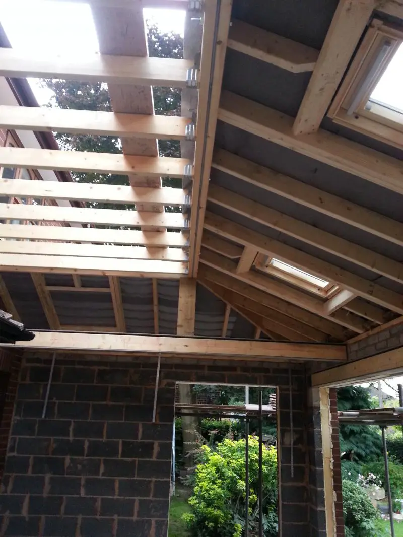
From the existing house, a 3 meter flat roof will be installed. From that point there will be a pitch of 18 degrees down to the 3 meter eaves of the front of the extension.
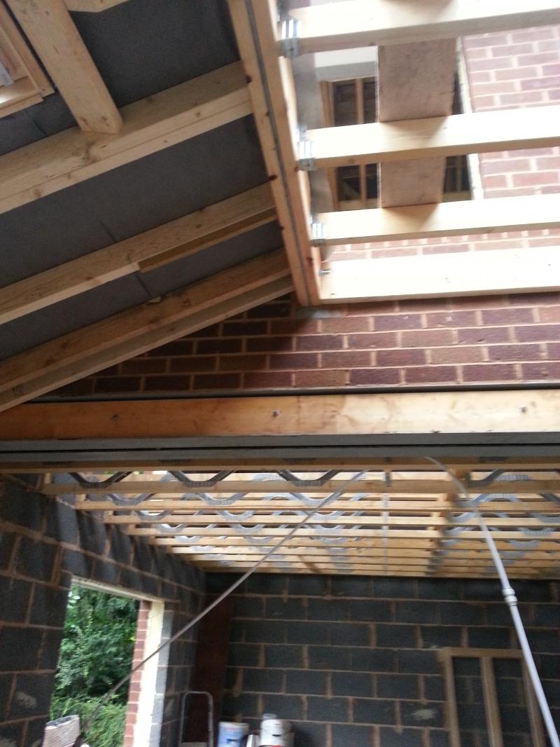
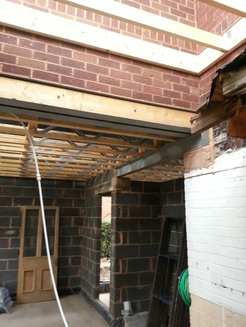
The situation is this, my builders want to build a wooden support frame which would sit under both sections of the roof to provide additional support. However this would create a false ceiling at the 3 meter mark.
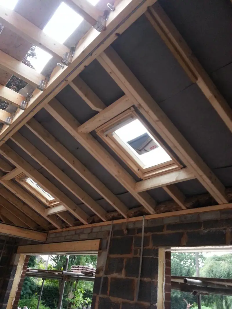
I want to retain this space to make the extension feel more spacious with more ceiling height. I would rather plasterboard onto the underside of the roof structure to maximise the space. My builder has told me that he worries about the strength of the structure, hence why I have instructed a structural engineer to design what will be required and what materials to use.
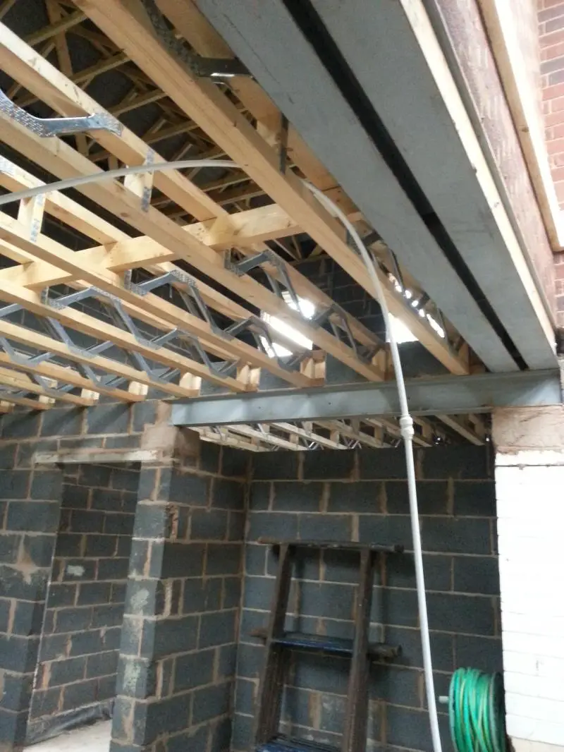
This image is what my builder wants to build
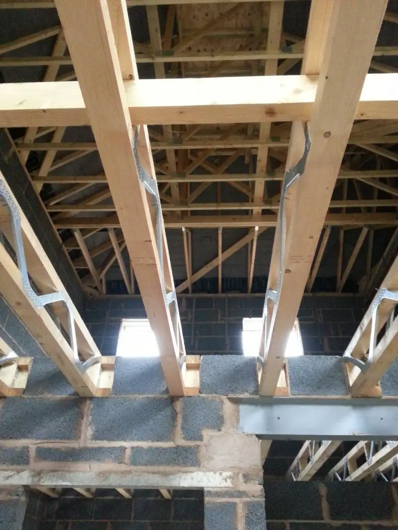
This image is more of what i'm after.
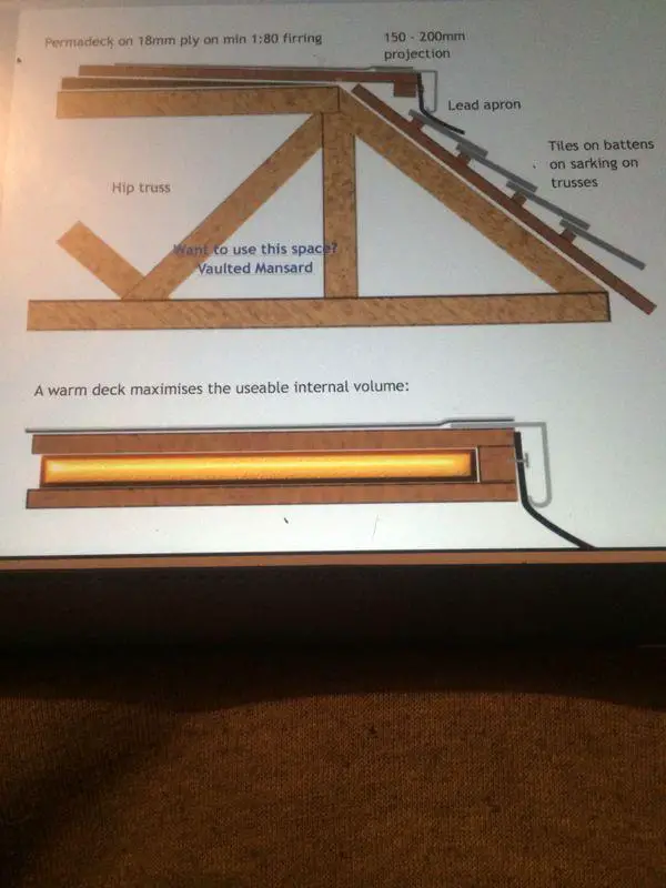
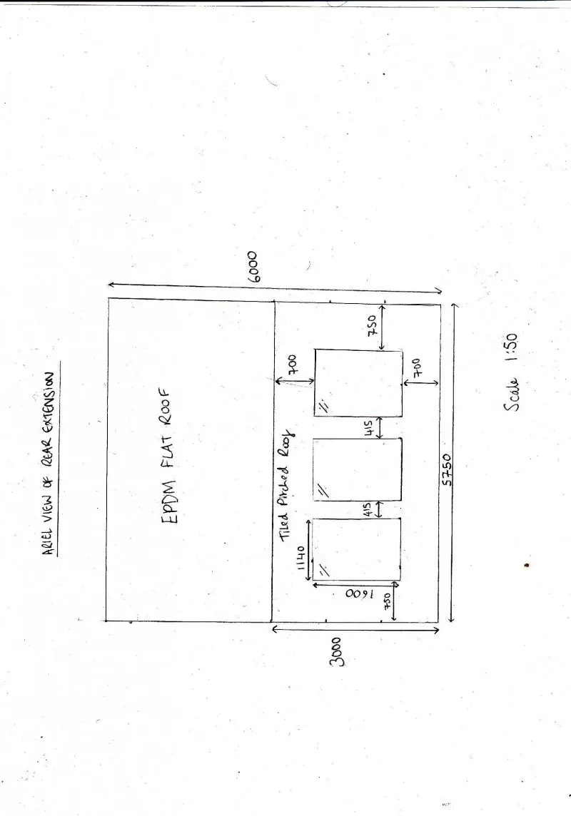
Birds eye view of the extension
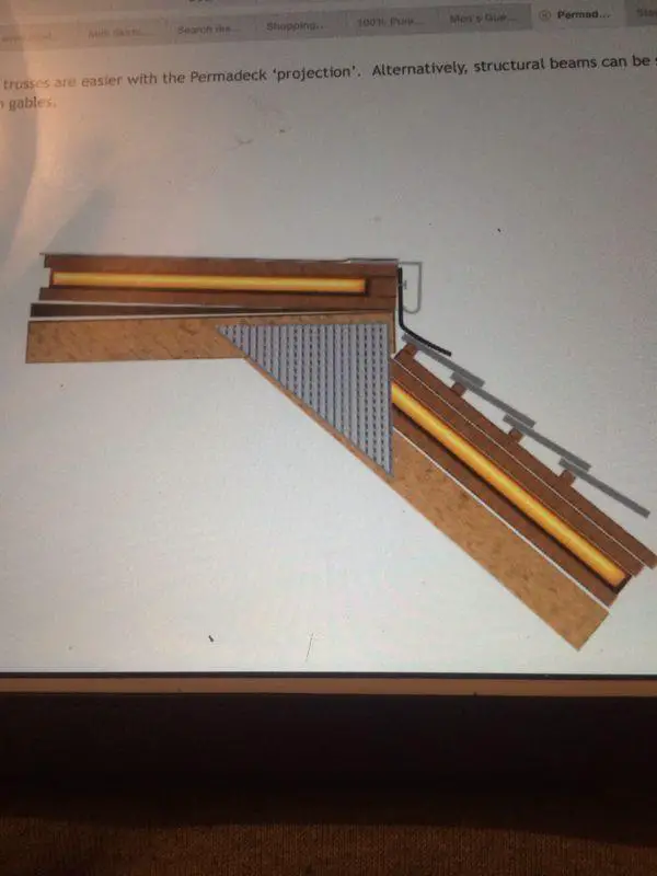
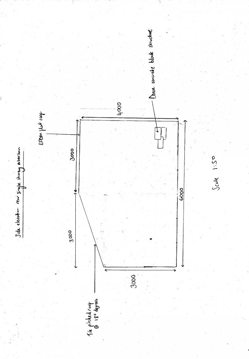
Side elevation of the extension
Any ideas or experience in this field guys?
All the best
Currently building my rear 6 meter extension. Not myself, but managing the build in and around work. Builders have thrown up the question and as such I have a structural engineer working on the plans of the roof but will not get back to me by Wednesday so I was hoping to see if anyone could shed some light on the situation before then.
Ok so, 6 meter extension from the rear of the house. 3 meters to the eaves and 4 meters to adjoin the existing rear wall of the house.
From the existing house, a 3 meter flat roof will be installed. From that point there will be a pitch of 18 degrees down to the 3 meter eaves of the front of the extension.
The situation is this, my builders want to build a wooden support frame which would sit under both sections of the roof to provide additional support. However this would create a false ceiling at the 3 meter mark.
I want to retain this space to make the extension feel more spacious with more ceiling height. I would rather plasterboard onto the underside of the roof structure to maximise the space. My builder has told me that he worries about the strength of the structure, hence why I have instructed a structural engineer to design what will be required and what materials to use.
This image is what my builder wants to build
This image is more of what i'm after.
Birds eye view of the extension
Side elevation of the extension
Any ideas or experience in this field guys?
All the best