Boilermate 2 constantly running pump

Joined
23 Jun 2008
Messages
51
Reaction score
0
Location
Norfolk
Country
United Kingdom
About time I started a thread with the correct title and all.

As some of you are aware, I have the Boilermate 2 constantly running pump problem. I've been advised by forum members (thanks - you know who you are) to change the PCB.

Question is which one?

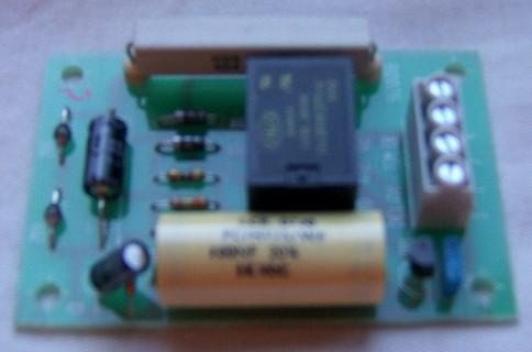
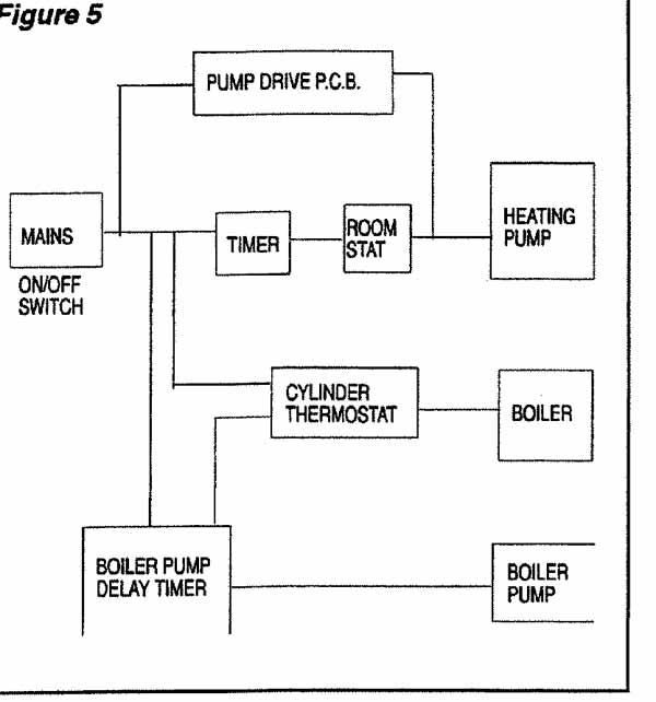
I went to the Pump Drive PCB first and found discolouration from heat scorching on the PCB. I started to undertake some resistance checks and damn near burnt myself on Delay Timer PCB. It turns out that the heat scorching originated from R1 on the Delay Timer PCB. I haven't had time to desolder for proper testing but resorted to a quick voltage check in situ. The right hand leg was at 125v and the left hand was at zero. This can't be right 125v dropped over one resistor, can it?. Does anyone know the R1s component data and value so as I can replace it rather than the whole board?

Many thanks,
Dave
 
Sponsored Links
Further update.

The wattage is determined by dimension, from specs on Maplins.

3W - 23mmx9mmx10mm
7W - 35mmx9mmx10mm
10W - 49mmx9mmx10mm

I just need resistance value now..............

Dave
 

Thats a fairly hefty resistor and if it's hot it has probably survived so far.

At a guess it is a mains dropper resistor which with the diodes and maybe a zener is supposed to provide a low voltage DC supply for the rest of the board, but that is just a guess.

I would check the diodes and the transistor which presumably switches the relay ON/OFF.


Does the pump connect directly to this board and what are the other connections to it?

EDIT: Just found a block diagram which suggests the Pump Drive PCB is used to control the Heating Pump and the Boiler Pump Delay Timer is connected to the Boiler Pump. Is it the Boiler Pump which runs permanently?

 
Sponsored Links
Its the Delay Timer PCB that is constantly providing a voltage directly to the boiler water circulation pump.

I know there is a known fault with the two capicators that is related to relay chattering. I think that R1 is okay, after a little research into wirewound resistors, and the heat scorch is because the pump is always on. If I had a list of components I'd be happy to change them all. The resistors are easy with colour codes but the Diodes are a not apparant.

A board circuit diagram would be handy, wouldn't it. I may have to get the PCB out tonight to photograph it and draw a circuit diagram......

Thanks,
Dave
 
Seems likely that when thermostat supplies power, the resistor/diodes provide DC to charge one of the capacitors and hold ON the transistor and relay driving the pump.

When mains from thermostat disappears the charged capacitor should be just enough to keep the transistor (and relay) powered ON for the overrun period.

Among other things it's possible either the mains power to this board from the thermostat isn't being cut OFF when it's up to temperature, or the transistor has shorted and is holding the relay ON permanently.

Far too much guesswork going on here though.
 
I can check to make sure power is going off from storage tank (but neon is going out so suspect its ok). I guess a new board is the way forward then? Damn, I hate being beat :(

Any recommendations for retailers?

Dave
 
Thanks for the info Jack,

I can confirm that the switched live to Timer Delay PCB goes on/off with the neon - working as advertised.

When I switch the system on, after being off for resistance checks, the pump did not run immeadiately. There was a 2-3 second silence, 2-3 second relay chattering and then the pump kicked in - even though the switched live hadn't demanded it.

The track at the top right by the wirewound resistor has continuity.

View media item 7470
View media item 7471
Any ideas?

Many thanks,
Dave
 
There isn't that much on the board really. Resistances are high values so it should be straightforward to check the diodes and the transistor in circuit.

If the zener diodes have failed they usually like going short circuit so that should be obvious. Looks like they are marked with an identification number which helps.
 
Diaster! Just found that I'm getting 42v on the S/L input when should be off. Could it be store thermostat? I'm off to check now!
 
Don't spoil the fun Dave - this is an ongoing text book example of how not to repair a BM2. :D
 
Don't spoil the fun Dave - this is an ongoing text book example of how not to repair a BM2. :D

:D

Gone full circle now! It turns out that the 42v supplying the Timer Delay PCB must be from the boiler. I've isolated the store thermostat to rule that out. Gone back to the Boiler (servicable according to Heat Team) and used the isolator switch to turn off the boiler and find the S/L drops to 0v.

What could cause the Potterton Suprima 40 S/L to be at 42v when off?

Dave
 
What could cause the Potterton Suprima 40 S/L to be at 42v when off?
Electrickery.

bulb.jpg
 

DIYnot Local

Staff member

If you need to find a tradesperson to get your job done, please try our local search below, or if you are doing it yourself you can find suppliers local to you.

Select the supplier or trade you require, enter your location to begin your search.


Are you a trade or supplier? You can create your listing free at DIYnot Local

 
Sponsored Links
Back
Top