Joined: 28 Apr 2009 Posts: 11 Location: Yorkshire, United Kingdom Thanked: 0 times
Posted: Fri Jun 26, 2009 6:59 pm Post Subject:
rwb2 programmer w/ mid position?
Greetings
help much appreciated
edited-- sorry for new long post
I bought a new [white] siemens rwb2e to replace an existing landis gyr rwb2
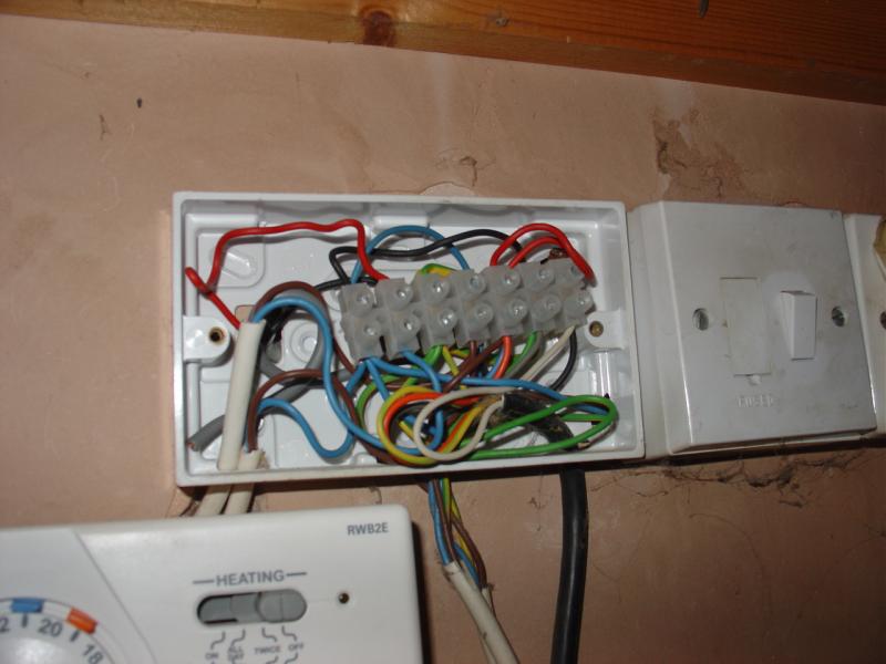
we have a pumped /gravity[?] fed ch/hw system, gas boiler, room stat, cylinder thermostat. the system also has an immersion heater in the cylinder
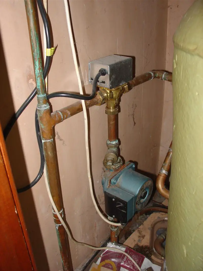
edit; in the photo below I now realise there is a valve.
edit*
I've read further and wanted to add some info.
what has been confusing me is;
there are 2 flats with identical heating/hw systems
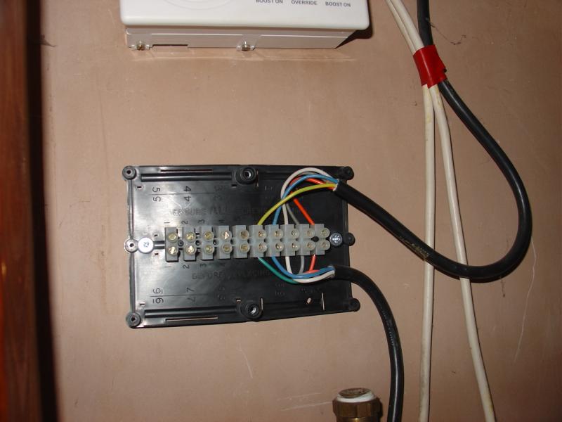
one flat has the original landis gyr programmer. it has a wire on "1" in the programmer
the other flat has had a new siemens rwb2 installed some time ago. but the wire on "1" in the programmer has been removed. a hand written note is also taped to the switch for the immersion heater, saying "do not use". I now think this may be a red herring which prompted my original question.
So now my question becomes,
is this a mid position system, so the programmer should be on 16 not 10?
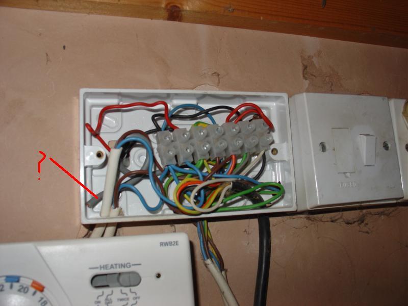
why would someone remove the "1" wire? how would this effect operation?
Joined: 18 Oct 2007 Posts: 3169 Location: Sussex, United Kingdom Thanked: 71 times
Posted: Sat Jun 27, 2009 9:57 am Post Subject:
The valve in the picture could be either a diverter or a mid-position; you can't tell from the photo. The diverter allows water to enter from the pump and then exit to one side or the other; the mid position also allows the water to exit from both sides at the same time.
It could be that you have a diverter valve, which does not need a wire connected to terminal 1 of the RWB2. The mid position valve does need the connection.
Joined: 28 Apr 2009 Posts: 11 Location: Yorkshire, United Kingdom Thanked: 0 times
Posted: Sun Jun 28, 2009 5:48 pm Post Subject:
the valves in both flats are honeywell v4073a1039 sundial Y plan diverter valves.
However the new siemens programmer [installed by a plumber] was set on 16, not 10, which explains some of the confusion/issues. [this is in the flat that had the 1 wire removed]
I've installed the other new siemens [set on 10] now in the second flat, and its working fine.
Ill now go ahead and install them in all the other flats
Just a note-- wickes had the siemens on clearance at a tenner a pop, and the digital siemens programmer [wickes H09? iircc] also
the valves in both flats are honeywell v4073a1039 sundial Y plan diverter valves.
One query resolved.
Quote:
However the new siemens programmer (installed by a plumber) was set on 16, not 10, which explains some of the confusion/issues. (this is in the flat that had the 1 wire removed).
That raises a new problem.
The difference between the 10 and 16 position is that when in the 10 position you cannot have the central heating on without having the HW on. This is relevant when you have pumped heating and gravity hot water.
But you have a fully pumped Y Plan system, which means you can have independent control over Hot Water and Central Heating. For this you have to set the switch to the 16 position, not the 10.
Which brings me to the disconnected wire in terminal 1. The other end of this wire should connect to a terminal which has the grey wire from the valve and a wire from the cylinder thermostat "satisfied" terminal. This is required so the valve can move to the CH only position. At the moment the valve can only be in the HW only position or mid position (HW and CH).
One reason for the strange wiring could be that the valve is faulty (one internal switch broken so the valve cannot move to the CH only position) and the plumber has deliberately hobbled the system so only HW or HW and CH are available.
Joined: 28 Apr 2009 Posts: 11 Location: Yorkshire, United Kingdom Thanked: 0 times
Posted: Mon Jun 29, 2009 1:30 pm Post Subject:
thanks for the reply
Im not exactly sure what I have!
there are 2 water tanks, one small, one large, for each flat. one gravity feeding the hot water,
as expected , the flat with the "one" wire cut, ch doesnt work on the "16" setting, unless you move both hw and ch manually.
on the other flat with the one wire intact, that doesnt work on the 16 either!?
the old programmers [installed circa 1985] , and all rwb2s, were all set on 10, although I couldnt obviously see a way to set them to 16. edit-- I now see the white plastic clip arrangement on the back for the 10/16]
Im not exactly sure what I have!
There are 2 water tanks, one small, one large, for each flat. one gravity feeding the hot water,
You are not the only one to be confused.
Gravity HW does not refer to how the water gets to the tap, but how the water in the HW tank is heated. "Gravity heating" depends on the fact that hot water is lighter than cold (lower density to be scientific) so the hot water will rise naturally from the boiler to the HW cylinder, pass through the coil transferring the heat to the water in the cylinder, and then return back to the boiler at a heavier density.
In your case the water leaves the boiler going through the pump and then divides at the valve. One path to the radiators and the other path to the coil in the cylinder. This is fully pumped.
Can you confirm that you have a cylinder thermostat about a thid way up the side of the cylinder. Looks something like this:
this is the one with the 1 wire cut (you can see it in the botton lh corner)
Do you mean the one I have marked?
If so, that's not a wire, it's a cable. How many cores (coloured wires) does it have?
This cable may have nothing to do with your central heating
Are any of the cores connected within the junction box - it's difficult to see?
Where does the other end go to?
How many cores does the cable to the cylinder thermostat have and how are they connected.
Unfortunately the original installer has only used a 7 terminal block - an 8-10 terminal block is usually used - so it is impossible to see if it has been wired correctly for a Y plan, which is what you should have.
I can tell you how to rewire the junction box. But first you will have to tell me what each wire of every cable connects at the other end. You will need a 10 terminal strip, or better still a wiring centre (cost about £10).
Also, can you let me know which boiler (make and exact model) you have?
Joined: 28 Apr 2009 Posts: 11 Location: Yorkshire, United Kingdom Thanked: 0 times
Posted: Thu Jul 02, 2009 8:18 am Post Subject:
thanks very much for the reply/help
the wire/cable in question has just one [red] wire in it. the other end is connected to the 1 terminal on the programmer
[the programmer is right next to the junction/spaghetti box so its easy to see all this].
so, if I understand this correctly, the plumbing is there for a fully pumped system, but the wiring is not/has never been connected correctly. so it wont function on the 16 programme.
thats a real head shaker, as its been like this from new !
my best guess is that when the [new] plumber replaced the programmer, he recognised the "16 position"/pumped plumbing,
he then installed a new junction box [as you suggest] but just did this with it. [which even I can tell does nothing...]
he then left the programmer on 16 position, which obviously didnt work the CH-- unless you manually moved both sliders
anyhoo...
thanks very much for the offer of further help-- it is greatly appreciated, but as we are doing a total rehab of all the flats next year, Im just going to leave them working in the 10 postion for now and deal with it all then.
the wire/cable in question has just one (red) wire in it. the other end is connected to the 1 terminal on the programmer. (the programmer is right next to the junction/spaghetti box so its easy to see all this.)
Understood. It just looks lime a grey cable which disappears into the wall. I cant see a grey cable going into the programmer; it must be hidden behind the two white ones.
Quote:
if I understand this correctly, the plumbing is there for a fully pumped system, but the wiring is not/has never been connected correctly. so it wont function on the 16 programme.
Correct. There is normally a wire between timer terminal one and the grey valve wire. Why it is not connected is the mystery.
Quote:
he then installed a new junction box (as you suggest) but just did this with it. (which even I can tell does nothing...)
Is the black cable entering at the bottom coming from the motorized valve? If so, that junction box is just a way of extending the black cable up to the other junction box.
Quote:
we are doing a total rehab of all the flats next year, Im just going to leave them working in the 10 position for now and deal with it all then.
It's not difficult to put it right - may take about 30 mins, but I understand the reason for your wanting to delay. Come back, preferably to this topic, when you want to proceed.
Joined: 28 Apr 2009 Posts: 11 Location: Yorkshire, United Kingdom Thanked: 0 times
Posted: Thu Jul 02, 2009 10:15 am Post Subject:
thanks again
the black wire does indeed come from the valve, but it is [more than] long enough to reach the old [white] junction box. the new [grey] junction box was added recently.
perhaps the [new] plumber thought about rewiring it correctly [when he was changing the programmer], and then changed his mind? who knows!?
You cannot post new topics in this forum You cannot reply to topics in this forum You cannot edit your posts in this forum You cannot delete your posts in this forum You cannot vote in polls in this forum