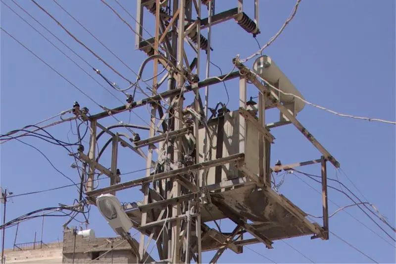
why is the u.k 240v?

Joined
30 Jan 2007
Messages
2,256
Reaction score
52
Location
West Midlands
Country
United Kingdom
Can someone explain the logic between the u.k being 240volt and america for example being 120volt.

Who decided what power each country should use? Which is better?

I 'think' there are only two differences in power around the world that are either 120 or 240 ? Why not 50v or 300v ?

Or is this a daft one like half the world drives on the left and the other half drive on the right for no real reason ?
 
Sponsored Links
I don't think that there is any reason as such, a few years ago there were different voltages for different parts of this country, an iirc some were infact DC.

There has to be a comprimise somewhere along the line, parts of the US use 110v/220v split phase system with the 220v used for larger appliances.
We just use 240v 50hz (or 230v ;) ) as it is probably a trade off between having large wires and dangerous voltage.
 
230V is the better system IMO.

As the voltage is higher, the current draw required to power the same sized light bulb is less. (Basic laws of physics). This allows the use of smaller (cheaper) cables, and also means we can have one large substation supplying lots of houses, where as in the US, they have lots of small transformers supplying just a couple of properties due to the issues of volts drom on their lower voltage supply.

Also, lower currents reduce the risk of cables and joints over heating, and allow more points on a single circuit, and as a result, smaller consumer units.

In the US, they operate on a split phase system (three incomming wires, instead of our two), using phase one to neutral and phase two to neutral as two 110V supplies, and phase one to phase two as a 220V supply for large loads suchs as heating appliances etc.

I can't honestly see the risk to the end user being much worse at 230V than it would be at 110V

I'm not sure who decided which system to use, or why.
 
so what is the advantage of 110v then? Why do they state we should use 110volt on building sites in the u,k unless rcd protected?


Is it also true that if we used high quality wire between our pilons that we could send just 240volts down them rather than say 50'000 volts or what ever it is due to volt drop? what is the reason for sending so many volts down the pilons over the u.k?
 
Sponsored Links
110V on a building site is for safety..

it's 55V from live to earth and 55V from neutral to earth..
so if you cut a wire and happened to touch it then you'd only have 55V through you..

again it's all to do with power..

power = voltage x current..
so to boil a 1000W kettle you need about 4A at 240V..

at 33,000V that's 0.03A..
if your wire can take 100A before starting to get hot then you can run 25 kettles at 240V, or 3333 at 33,000V
 
Mrs Secure does drink an awful lot of tea, but even she gets by with fewer than 3333 kettles.
 
yes but there's more than 25 kettles on the average housing estate.., not to mention showers, cookers, washing machines etc..
 
Voltage selection is a compromise. On the one hand lower voltages are generally less likely to kill you if you should come into contact with them and require less insulation and safety features. On the other hand lower voltages mean you need far bigger cables to keep the losses acceptable (if you halve the voltage you have to quadruple the cable size to get the same loss). The americans went for a lower voltage and relatively simply accessories. We went for a higher more effeciant voltage but as a result had to put a lot more effort into safety features on our plugs and sockets to get a similar level of overall safety.
 
Who decided what power each country should use?
On the Wikipedia web site said:
In the 1880s only carbon-filament incandescent lamps were available, designed for a voltage of around 100 volts. Later metal filament lamps became feasible. In 1899, the Berliner Elektrizitäts-Werke (BEW), a Berlin electrical utility, decided to greatly increase its distribution capacity by switching to 220 volt nominal distribution, taking advantage of the higher voltage capability of metal filament lamps. The company was able to offset the cost of converting the customer's equipment by the resulting saving in distribution conductors cost. This became the model for electrical distribution in Germany and the rest of Europe and the 220-volt system became common. North American practice remained with voltages near 110 volts for lamps.

In 1883 Edison patented a three wire distribution system to allow DC generation plants to serve a wider radius of customers. This saved on copper costs since lamps were connected in series on a 220 volt system, with a neutral conductor connected between to carry any unbalance between the two sub-circuits. This was later adapted to AC circuits. Most lighting and small appliances ran on 120 V, while big appliances could be connected to 240 V. This system saved copper and was backward-compatible with existing appliances. Also, the original plugs could be used with the revised system.
 
Both the UK and USA in the beginning had many different voltages and distribution methods. Most of the standardisation in the UK was worked out during the second world war and the 13A plug and socket and 240vac @ 50Hz for most of the UK was fixed as we started on the national grid which was around 1960's with the national grid we transmitted power further than USA where they were powered at that time town by town.

As with many things there is a trade off. The higher the frequency the smaller the transformers but the lower the less are the power line losses. Aeroplanes use 600Hz and fluorescent lamps can be in gigahertz range as are computer power supplies.

Connection to the rest of Europe is DC.

Because we have now 230vac dropped 10 volt to line up with Europe we have large transformers which produce 3 phase with one phase being feed to each house in turn so you will be on same phase as 3 doors up the street.

However the USA use split phase and a single phase transformer is used to supply just half a dozen houses.

Some places with 230vac also use the small transformer method this
is in Turkey where 3.3Kv is feed to small transformers which then supplies 230 to the dwelling more than in USA may be 20 or more flats from each transformer but less than UK.

USA still have 220vac into each house with one leg upstairs and one leg down stairs and both to the cooker.

1980 in Algeria they had three phase 110 with 110vac to centre neutral and 190vac between phases and there was a problem getting air conditioner units as 220vac units would fail on 190vac and one had to use auto-transformers to boost to 220vac.

On large building sites we have 64vac to earth but no neutral supply so two 64vac lines gives us 110vac on smaller sites single phase is used with 55vac to earth. The same with 230vac in built up areas three phase is used so 400vac between phases and 230vac phase to neutral but in the country single phase is used normally split phase with 460vac phase to phase and 230vac phase to neutral these are the small transformers we see up the poles.

On mainland UK 3.3Kv and 11Kv is used but Northern Ireland (Ulster) is 10Kv

New York still had DC supplies in 2000 mainly for lifts and in UK in 1960 I know of one town in Mid-Wales with 110vdc supply and the National grid did not reach some village outside Bala until after 2000.

But in this country most industrial premises have same voltage as domestic but in USA 550vac and 660vac is common in industrial premises even here mines and quarries often use the higher voltages. In Hong Kong the incoming supply where I worked was 11kv and it was transformed down to 10kv and delivered on flexible cables to main machine where it was transformed to 660vac between phases for main motors and further to 220 volt between phases for control and lighting using delta secondary and IT system.

I would guess something similar when they dug the channel tunnel?
In industry even in this country you will see the purple (24v) and white plugs used with isolation transformers often for confined spaces.

For some more info see War of Currents
 
I thought Lord Weir created the first part of what became the National Grid in 1925 - is the Wiki incorrect in claiming that the network became national in 1938?
 
Because we have now 230vac dropped 10 volt to line up with Europe we have large transformers which produce 3 phase with one phase being feed to each house in turn so you will be on same phase as 3 doors up the street.
not always true.

our street is supplied in banks of 4 or 5 houses.

theres 3 phase supply under the pavement. every 4 or 5 homes takes a single phase from this and its daisy chained to the 4/5 homes. Not directly through cutouts, but around the outsides of homes with spurs off. All done in concentric / seperate twin / combined twin oval cables.

terrace homes are often done in pairs, as the supply is under the stairs and two staircases will be side by side. Or the supply is next to the bay window in the lounge, as is next doors etc.
 
I thought Lord Weir created the first part of what became the National Grid in 1925 - is the Wiki incorrect in claiming that the network became national in 1938?

The National Grid was developed over some time. I was not around in 1938 to 1951 so don't remember but in 1960's I remember the National Grid being expanded to include most parts of the UK with pylons springing up all over the place.

Because we have now 230vac dropped 10 volt to line up with Europe we have large transformers which produce 3 phase with one phase being feed to each house in turn so you will be on same phase as 3 doors up the street.
not always true.

our street is supplied in banks of 4 or 5 houses.

theres 3 phase supply under the pavement. every 4 or 5 homes takes a single phase from this and its daisy chained to the 4/5 homes. Not directly through cutouts, but around the outsides of homes with spurs off. All done in concentric / seperate twin / combined twin oval cables.

terrace homes are often done in pairs, as the supply is under the stairs and two staircases will be side by side. Or the supply is next to the bay window in the lounge, as is next doors etc.

Yes there are many different methods used. In Algeria we supplied 3 phase to each cabin with one phase to each room and we did get to odd neutral pin burning out and the problems as a result.

But since the War of Currents new methods of converting AC to DC and back to AC have been developed and we can now run 60Hz motors in UK without much of a problem since the development of the inverter.

But since in the UK the power distribution was Nationalised all voltages and frez became the same with few odd exceptions. But in USA they have still quite a few different systems running at the same time. The "Hot Wire" method of earthing delta secondary on transformers is something we never see here and I hope we never do.
 
Is it also true that if we used high quality wire between our pilons that we could send just 240volts down them rather than say 50'000 volts or what ever it is due to volt drop? what is the reason for sending so many volts down the pilons over the u.k?

For a very long time there has been talk of warm superconductors which would allow you to send 100,000A's down a cable which if it were standard materials would be only good for perhaps 100A.

I think its going to be a very long time before that happens as its yet to become practical outside of a lab.

A typical 1.2GW power station will export quickly onto 132kV pylons. This power at 132kV works out at 5250A per phase. Probably can be handled by 1-2 pylons with 4-2 conductors per phase.

At:
33kV this would be 21,000A per phase
11kV, 63,000A/Phase
400v, 1,732,050A per phase!

As you can guess, 1.7 Million Amps would need quite a large cable if you exported at 400V (230v single phase) from a power station.


With regards to cable losses, the loss is power where:
Power Loss = Current x Current x Resistance

So if you have 1000A going down a cable with a resistance of 1Ohm then you will lose 2MW of energy in heat per phase, or 6MW total 3 phases. You may get 1Ohm after around 15kM of 700mm.sq cable, so your losing about 400W per M of pylon!
(im using hopefully educated guesses here so if somebody knows a more real life example then let me know)

If that 1000A is at 132,000V then you are moving 230MW
So your loss is 2.61% which isnt too much

If your 1000A is at 11kV, then you are moving 19MW
so your loss is 31.6% which is quite allot!

Look at it this way, 50A at the following voltages delivers the following power:

12V 600W
110V (1Ph) 5.5kW
230V (1Ph) 11.5kW
400V (3Ph) 36.6kW
660V 57.1kW
6.6kV 571kW
11kV 1MW
33kV 3MW
132kV 12MW

For 50A you may use 10mm.sq cable. So you can get between 600W and 12,000,000W down your 10mm.sq cable depending on the voltage.

You do have transformation losses to get the HV, but most HV transformers are better than 98% efficiency at each end. Large 200+MW transformers can be around the 99% efficiency mark!

I believe you can get 99.9% if you start to go down the superconducting transformer route but nobody does this in practice.


Stuart

(ps. i hope i got my sums right!)
 
Although what "stuartsjg" says is correct although I have not checked his sums the main problem would be volt drop.

On a site I worked on "Mount Pleasant Falklands" we had a generator shed with 10 x 500KVA generators to supply the accommodation block. These all generated at 400 volt phase to phase. But by time this was cabled to limits of camp it would have been well below 400 volt so we transformed up to 3.3Kv at the end of generator shed and back down local to the area each transformer supplied.

This did cause problems as we needed at least 6 generators running to take transformer in-rush and if you have ever tried to sync 6 generators with hardly any load you would know the problem getting them on line without knocking each other out on reverse current.

It also of course meant using a lot lighter cables both because of thickness and because they were Ali-cables. Ali-cables don't seem to like low volts but preform great with high volts.

Once the site went onto permanent generators then the main Ruston 1.5Mw generators had an output of 11kv so only step down transformers were required.

Both 11kv and 3.3kv voltages were used on final site.

I was involved with some 750Mw and some 600Mw generators at Sizewell and Connah's Quay but can't remember output voltage. I know there was an 11kv feed to AVR as someone made a mistake and fitted a 6Kw transformer to power 3 x 3Kw fans seems the French are not too good at maths! I think output was 11Kv but not sure.

But when you start to get to big stuff there are all sorts one would not think about like hollow wires with Hydrogen pumped around them for cooling on rotor and deionised water in stator. Generating at higher voltages does mean smaller generators of course. Which in turn has an effect on so much else. Battery backed lub pumps etc. Sizewell had quite a few Ruston generators for backup to allow it to close down safely I think from memory 6 x 1.5Mw back-up generators at with 11Kv output.

Main circulating water pump was 11Kv again to reduce size of motor.

Even ElectroHaul trucks ran with 11Kv motors on each wheel and not distance for power to travel
equip5.jpg
who says Auto-Electricians only work on low voltage?
 

DIYnot Local

Staff member

If you need to find a tradesperson to get your job done, please try our local search below, or if you are doing it yourself you can find suppliers local to you.

Select the supplier or trade you require, enter your location to begin your search.


Are you a trade or supplier? You can create your listing free at DIYnot Local

 
Sponsored Links
Back
Top