Wiring an electric roller shutter . .

Joined
27 Dec 2006
Messages
552
Reaction score
6
Location
London
Country
United Kingdom
Hi all,

Yesterday I had to remove a junction box in the wiring for my shops electric roller shutter in order to plasterboard around it. I took photos of the connections and made a quick diagram on a bit of plasterboard. I then gaffered the plasterboard to the junction box - MISTAKE! At the end of the day when I cam to rewire the gaffer tape pulled my diagram off !! The photos didn't prove to be much help either . . Now when I try and rewire it pops the fuse . HELP!

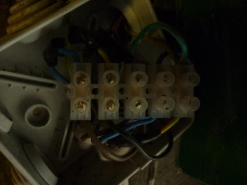
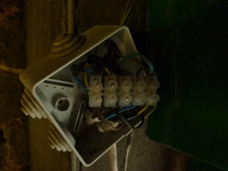
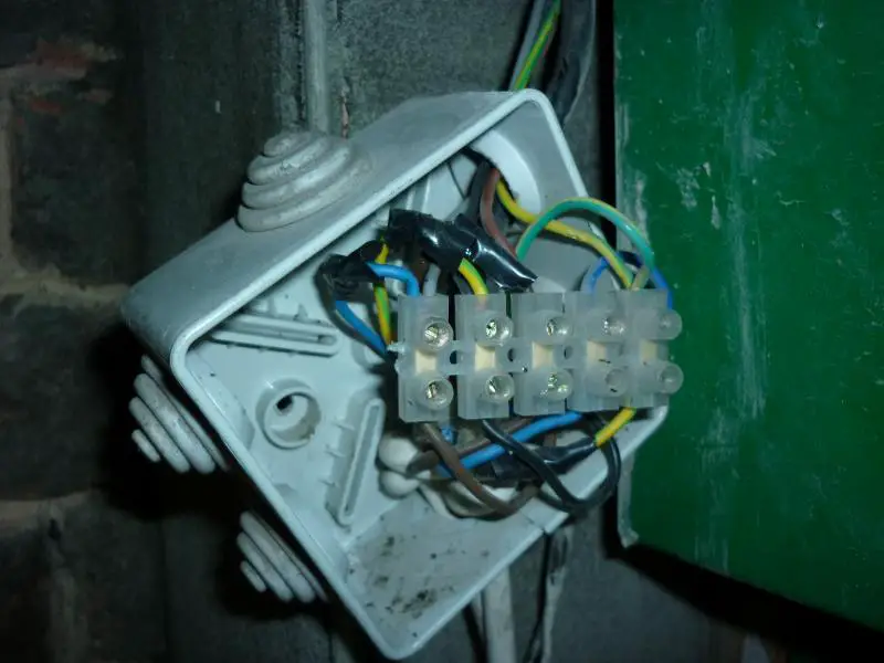
there are 4 cables coming into the junction box and a 5 way connecting block in box.

cable one is obvious - its the power and has 3 cores - brown, blue and green/yellow.

cable two goes to the up/down switch in the shop - again it has 3 cores - brown, blue and green/yellow

cable 3 and 4 go off into the top of the shutter and so I can't tell which goes to the motor, and which to the key operated up/down switch on the street . . .but . .

cable 3 has 4 cores - brown, black, blue and green/yellow

cable 4 also has 4 cores - brown, black, grey and green/yellow.

the shutter worked perfectly before I disconnected it , and I do remember that a black was connected to an earth? strange . .

can anyone help?

thanks!

Huey
 
Sponsored Links
How many terminals being used in the JB?

Think you will need to find out whats at the end of the 2 3-core cables at least or it'll be the crystal ball pic for you!
 
Huey have you got any kind of meter to test resistance and voltage?

Think it will be a god send in this instance and you could get one pretty cheap if you haven't ?
 
all 5 terminals on the connecting block were being used - here are the 2 photos I took - wish I'd paid more attention but figured with it all written down I couldn't go wrong . . . .


I did try an establish which cable went to motor and which to outside switch today but didn't seem to be able to get to the terminals on the back of the key operated switch. . . . .
 
Sponsored Links
I do have a multi meter, but afraid I don't know how to use it in this situation . . . .any advice most welcome!

cheers
 
cable one is obvious - its the power and has 3 cores - brown, blue and green/yellow.

Ok, so that's your L/N/E supply.

cable two goes to the up/down switch in the shop - again it has 3 cores - brown, blue and green/yellow

the shutter worked perfectly before I disconnected it , and I do remember that a black was connected to an earth? strange . .

The up/down switch will require a permanent live, and then will output two switched lives, one for up and the other for down. It seems as if someone has used the earth for carrying power which, as you suspect, is wrong. This cable really needs to be replaced with 4-core before you go any further. The green/yellow CPC should never be used as anything other than an earth conductor.

cable 3 and 4 go off into the top of the shutter and so I can't tell which goes to the motor, and which to the key operated up/down switch on the street . . .but . .

cable 3 has 4 cores - brown, black, blue and green/yellow

cable 4 also has 4 cores - brown, black, grey and green/yellow.

You should be quite easily able to identify which cable goes to the key switch. With the power and wiring disconnected, pick one of the cables and put your multimeter on continuity/beeper setting, one probe to brown and the other to black. Assuming the original installer has chosen to use brown as common/permanent live, you should find that the reading on the meter changes between open and short circuit, give or take an ohm or two for the resistance of the wiring.

I'm surprised you can't work back from your pictures - they seem to be detailed enough, especially if that tape is still present on the wiring. If all else fails, a good electrician would be able to fix this for you within half an hour, although it'll take a little longer to run in a replacement cable for that 3-core to the indoor up/down switch.
 
thanks very much Mathew . . .. it's no problem to replace the internal switch cable for 4 core - nothing is buried and I have available cable.
I will be able to try the test with the meter tomorrow to identify which of the other cables goes to the switch - so, assuming I am armed with this knowledge - then what?

thanks again

Huey
 
I will be able to try the test with the meter tomorrow to identify which of the other cables goes to the switch - so, assuming I am armed with this knowledge - then what?

You'll have to experiment with the shutter a little to find out which core controls which direction. I suspect cable 3 goes to the shutter on account of it containing a blue core, as the motor will obviously require a neutral. However, given that the original installer decided to use a CPC as a live conductor, it's not really a good idea to make any assumptions.

To make things easy for yourself, take some light coloured insulation tape and a fineline marker pen. Firstly identify the connections to the outside key switch. Hopefully you'll find continuity between brown/grey when it's in one position, and brown/black in the other. If that turns out to be the case then you know that brown must be common, and the remaining two cores can be labelled up/down as appropriate.

Once you've done this, you'll also now know which of the remaining cables supplies the shutter, so now you should be able to test it. Set your meter to measure resistance/Ohms. The 200 Ohms range should be OK, assuming it's not an auto-ranging meter. Measure between brown/blue and then black/blue. Working on the assumption that blue is neutral, you should get a reading on one of these pairs only, and open circuit on the other.

The shutter will incorporate microswitches to prevent it travelling too far, so as long as the shutter is currently stuck either fully open or fully closed, the core pair that provides you with a low ohms reading will be the one that makes the motor travel in the opposite direction to its current position. For example, if the shutter is currently stuck down and you measure a resistance between black/blue, these are the two conductors that, when linked, will cause the shutter to move upwards and open. If the door is stuck halfway between the two positions, you will either have to test by applying power and observing the movement of the door, or take a gamble!

Again, it should now be easy for you to identify the up, down and neutral connections to the motor.

We'll ignore the indoor switch, as you're going to re-cable it, so it will be obvious without the need for testing as to which conductor is which. Again, label these as common/up/down.

The incoming supply is also pretty self-explanatory, label it Live/Neutral/Earth.

All four of your green/yellow conductors will need to connect together in a single terminal. Don't do this until you run in the new 4-core, otherwise you may cause a short circuit with the existing 3-core utilising the CPC as a power conductor.

All cores labelled 'up' will need to go to another terminal. A third terminal should be used for all those labelled 'down'.

Take all the 'common' conductors and place those in a terminal, along with the incoming 'Live' supply.

Take the 'neutral' conductor from the incoming supply, and link it in a 5th terminal to core you labelled 'neutral' that goes to the shutter motor.

Let us know how you get on.
 
Just use the winding rod :LOL:

(Most shops that have electric roller shutters keep the winding rod inside the premises . . . . Logic or what!!!)
 
didn't seem to be able to get to the terminals on the back of the key operated switch. . . . .
Usually, a small screw on the front is undone to remove the cover plate, then inserting the key, rotating it part way and pulling on it will remove the switch assembly from the housing.
 
I will be able to try the test with the meter tomorrow to identify which of the other cables goes to the switch - so, assuming I am armed with this knowledge - then what?

You'll have to experiment with the shutter a little to find out which core controls which direction. I suspect cable 3 goes to the shutter on account of it containing a blue core, as the motor will obviously require a neutral. However, given that the original installer decided to use a CPC as a live conductor, it's not really a good idea to make any assumptions.

To make things easy for yourself, take some light coloured insulation tape and a fineline marker pen. Firstly identify the connections to the outside key switch. Hopefully you'll find continuity between brown/grey when it's in one position, and brown/black in the other. If that turns out to be the case then you know that brown must be common, and the remaining two cores can be labelled up/down as appropriate.

Once you've done this, you'll also now know which of the remaining cables supplies the shutter, so now you should be able to test it. Set your meter to measure resistance/Ohms. The 200 Ohms range should be OK, assuming it's not an auto-ranging meter. Measure between brown/blue and then black/blue. Working on the assumption that blue is neutral, you should get a reading on one of these pairs only, and open circuit on the other.

The shutter will incorporate microswitches to prevent it travelling too far, so as long as the shutter is currently stuck either fully open or fully closed, the core pair that provides you with a low ohms reading will be the one that makes the motor travel in the opposite direction to its current position. For example, if the shutter is currently stuck down and you measure a resistance between black/blue, these are the two conductors that, when linked, will cause the shutter to move upwards and open. If the door is stuck halfway between the two positions, you will either have to test by applying power and observing the movement of the door, or take a gamble!

Again, it should now be easy for you to identify the up, down and neutral connections to the motor.

We'll ignore the indoor switch, as you're going to re-cable it, so it will be obvious without the need for testing as to which conductor is which. Again, label these as common/up/down.

The incoming supply is also pretty self-explanatory, label it Live/Neutral/Earth.

All four of your green/yellow conductors will need to connect together in a single terminal. Don't do this until you run in the new 4-core, otherwise you may cause a short circuit with the existing 3-core utilising the CPC as a power conductor.

All cores labelled 'up' will need to go to another terminal. A third terminal should be used for all those labelled 'down'.

Take all the 'common' conductors and place those in a terminal, along with the incoming 'Live' supply.

Take the 'neutral' conductor from the incoming supply, and link it in a 5th terminal to core you labelled 'neutral' that goes to the shutter motor.

Let us know how you get on.

I hope this advice is wrong, what happens if the indoor switch is moved to up and the outdoor switch is moved to down?
 
The shutter will be compressed into a black hole, and if you are within its event horizon Bad Things will happen to you.
 
I hope this advice is wrong, what happens if the indoor switch is moved to up and the outdoor switch is moved to down?

It's a fair point, and something I actually hadn't considered. That said, with the information that's been provided, I can't see how else it could have been wired originally. I can only assume that these doors are either not designed with that failure mode anticipated, or they will cope with it just fine.

I think you have described accurately the way it was wired and using the picture I could describe wire for wire how to reconnect it but I would only be describing whats in the picture and assuming [always silly] the OP has already achieved what I see and understand then I guess I have misinterpreted something. for this reason, like you, I am a surprised the OP was unable to reinstate this himself.

I'm a little saddened it was wired like this in the first instance.
I would expect the stalled motor to either blow the fuse or better have overheat protection. Either way it would be better if it were wired in a way that this could not happen and its probably easier than you think.
 

DIYnot Local

Staff member

If you need to find a tradesperson to get your job done, please try our local search below, or if you are doing it yourself you can find suppliers local to you.

Select the supplier or trade you require, enter your location to begin your search.


Are you a trade or supplier? You can create your listing free at DIYnot Local

 
Sponsored Links
Back
Top