completing a half finished CH install

Joined
31 Dec 2010
Messages
13
Reaction score
0
Country
United Kingdom
Hi all.

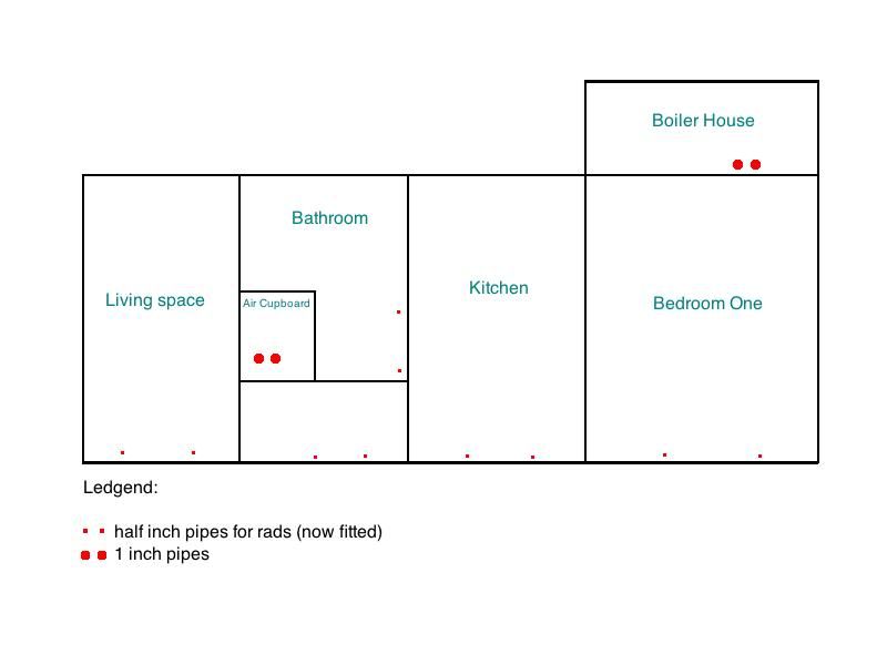
My father in law has a holiday home/cottage and back in '91 he had a n extension fitted and the whole place was renovated. As money was tight CH was not fitted but he did manage to have the pipework buried int he new concrete floors.

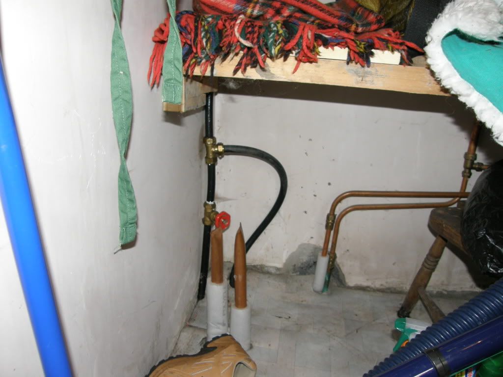
So, every room has two pipes for a rad - 5 in total - and there is 2 1"pipes in the airing cupboard and two pipes in the attached concrete shed for the boiler.

I've fitted the rads and I'd hoped to fit a 2-zone heating kit. Like this here.

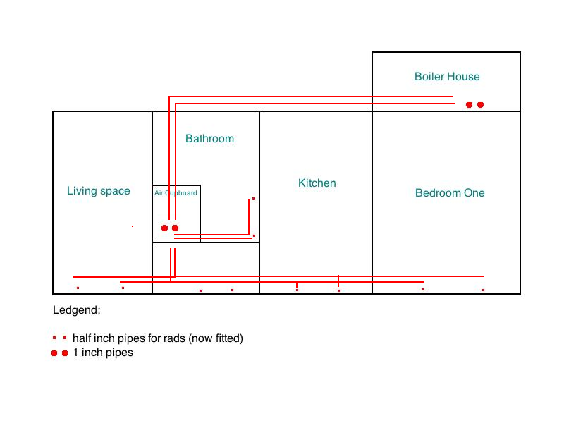
But I fear the worst. There is no way of knowing the pipe layout and I intended doing an s-plan layout so both HW and CH can be controlled independently.

Does anyone know of any tricks or tests to workout the pipe layout and see if I can even seperate both the pipes to the coil and the rad system?

Adam
 
Sponsored Links
The two pipes in the shed for the boiler are the primary flow and return pipes for the boiler, which I assume are the two pipes coming up in your airing cupboard. Blow down them to double check, with someone at the other end. Where are the pipes from the airing cupboard to connect to the CH flow and return pipes? Suggest you look at a typical layout drawing of a CH system which you can relate to the cottage first. :confused:
 
If it was copper pipe, I'd be a bit concerned about there condition burried in concrete for 20 years.
 
Sponsored Links
You can identify pipes in concrete by capping and blowing into the supply pipe to see if the other end is open or not.

Tony
 
The two pipes in the shed for the boiler are the primary flow and return pipes for the boiler, which I assume are the two pipes coming up in your airing cupboard. Blow down them to double check, with someone at the other end. Where are the pipes from the airing cupboard to connect to the CH flow and return pipes? Suggest you look at a typical layout drawing of a CH system which you can relate to the cottage first. :confused:

Thanks. I understand the typical layout but the only exposed pipes in the whole layout are two 1-inch pipes in boiler house (primary flow and return for boiler to be fitted to) and two 1 inch pipes protruding out of the airing cupboard concrete floor. That's it. What I'm presuming is that the flow to radiator pipes tee's off under the concrete. Does that make sense?
 
Ok, I've tried to sketch what's going on. This picture shows The pipes as they are.

SligoCottage-CHlayout001.jpg


and this is how I'm guessing (!) the pipes are layed out under the concrete.

SligoCottage-CHlayout002.png


If they are I will simply dig up a small area of the concrete floor in airing cupboard to expose where they tee off ond re-do the pipework to incorporate motorised valves right?!
 
To assume anything makes an (ass of u and me) check under airing cupboard for those CH flow and returns. As regarding the copper pipes it's not corrosion from the inside it's if they were protected within the concrete :(
 
...As regarding the copper pipes it's not corrosion from the inside it's if they were protected within the concrete :(

Ah right. Well they all have thick white insulation on them that can be seen at the floor finish.

I will triple check (already double checked!) for the CH flow and return pipes to rads (not the invertor coil ones there) but I'm almost certain theyre not there :(
 
If you find the Ch flow and returns in the airing cupboard tee'd off then it's been piped up wrong. Until you find them can not go any further on this thread. From your diagram it looks the most likely place. Even though you say it's got 'white insulation?' I would not be happy unless I'd have done an air pressure test.
 
Just use a vacuum cleaner to suck air through the various ends to identify what is connected to what.

If there is an under floor connection between the primaries and the heating it will become apparent.
 
Hi all.

There is DEFFO no other pipes in the air cupboard other than these:

P3070004.jpg


the two half inch pipe in background are hot and cold supply going down and through to the shower.

The two 1 inch are for the hot tank inverter coil.
 
Probably best to ignore RichieHoneybucket, he is a known troll who has been barred a number of times, and this is his latest alias.
He has never worked in the trade in any way shape or form.

As for your problem, any decent installer should be able to sort it for you.
 

DIYnot Local

Staff member

If you need to find a tradesperson to get your job done, please try our local search below, or if you are doing it yourself you can find suppliers local to you.

Select the supplier or trade you require, enter your location to begin your search.


Are you a trade or supplier? You can create your listing free at DIYnot Local

 
Sponsored Links
Back
Top