Generator back-up system

Joined
28 Jan 2011
Messages
56,193
Reaction score
4,176
Location
Buckinghamshire
Country
United Kingdom
I think this is probably still OK, but would appreciate any comments....

Something approaching 20 years ago, following a period of significant power cuts, I made some provision for generator back-up to maintain the CH system and a modicum of lighting during power cuts. Ironically, although it’s been tested fairly regularly, I don’t think it’s ever really had to be used in anger!

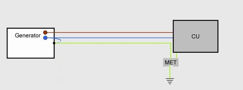
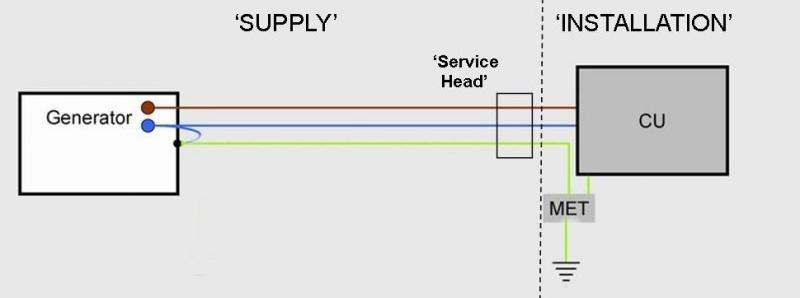
Rather than getting involved with a C/O switch, at the time I decided to go with a totally separate ‘installation’ for generator derived power. There is a (2kW, I think) portable genny located in an outhouse. Its output is plugged into a wall mounted (male) 16A ‘socket’ and thence via underground SWA to the house.

In the house, there is a mini DB/CU for the generator supply, with a 30mA RCD and a single 6A MCB. This ‘installation’ has a TT system of its own (the house is also TT), with its own earth electrode, and also has MPB. The one (6A protected radial) final circuit supplies a few lights scattered around the house (dedicated, totally separate from main house lighting), now CFLs, and a couple of sockets, all of which are clearly labelled. One of the sockets is designed to serve the CH system. The entire central heating electrical system (boiler, timers, pumps and motorised valves) is normally supplied via a single 13A plug (3A fused) plugged into a socket on one of the ordinary RFCs (rather than the more usual connection via a FCU). The ‘generator-supplied socket’ is adjacent to this one, so that the entire CH system can be unplugged from ‘the mains’ and plugged into it if necessary (without the need for a C/O switch).

This system appears to be in no way ‘broken’ (and probably even compliant with current regs), so I personally don’t see any need to have it ‘mended’ in any way. Any comments?

Kind Regards, John.
 
Sponsored Links
I see nothing wrong with the set-up. I wonder why you ask? Has some one suggested there is something wrong?

Since pipes will be bonded on both systems I would assume both earth rods are connected together. So do wonder why you have two? See nothing wrong with two however just confirming bonding which would mean both systems connected together.
 
I see nothing wrong with the set-up. I wonder why you ask? Has some one suggested there is something wrong?
Thanks. No, no-one has suggested that anything's wrong. I'm just systematically working my away around my electrical installation (extensive and complex, for a domestic property) in order to get a feel for what might need (or, at least, might benefit from) attention.

Since pipes will be bonded on both systems I would assume both earth rods are connected together. So do wonder why you have two? See nothing wrong with two however just confirming bonding which would mean both systems connected together.
It's a good question, and it is so long ago that I did it that I'm struggling to recall my thinking! It may well have been that, since the main installation's MET and the generator-supply CU/DB are a long way apart, I was simply trying to avoid the need for a substantial (and not easy to route) G/Y cable between them. However, particularly given that the two earth electrodes are in different places (on opposite sides of the house), I guess it has the effect (via the MPB conductors) of improving the mains installation's earth connection! I certainly can't think of any good reason to remove it.

Kind Regards, John.
 
Sponsored Links
Is the neutral earth link present in the generator?
How do you mean the generator has a TT system of it's own?
It is often confusing but what you are more likely to have is a TN-S or an electrically separate system (no N-E link) with a small 2kva genny. The norm in this situation is the electrode being the means of earthing.
That is unless of course you have an electrode tied to the neutral in the generator which is not directly connected to your house, using the general mass of earth for the connection to your house?
 
would have probably been cheaper to install a changeover switch
Well, it's all ancient history, but it's difficult to see how I could have achieved the same with a changeover switch without appreciably more hassle and cost. A c/o switch just for the CH circuit would have been straightforward enough, but would in itself have cost more than a plug and socket.

You are perhaps suggesting that the RCD and MCB in the genny DB, and the separate lighting circuits could have been avoided if I had used a c/o switch. If I had wanted to maintain some protection, that would presumably have required the c/o switch to switch the supply to the entire CU. Whilst that would be fine as far as the CH was concerned, one would then have had to remember to switch off most of the other circuits and/or loads connected to them before powering the CU with a small genny. In any event, to use the existing lighting circuits, and attempting to switch them to the genny would have been far more of a problem. Some lighting circuits do indeed come from the same CU as the CH, so could have been supplied with generator-derived power via that CU. However, lighting circuits in many parts of the house come from different CUs (indeed, different phases), so a very messy situation of multiple changeover switches would presumably have been required if I wanted to have some lighting available in most parts of the house. I could, of course, have avoided that by installing extra lights around the house fed from the 'CH CU' (with just the single c/o switch), but that would have got me almost back to where I am.

However, maybe I'm missing something, and there would have been an easier way of achieving what I wanted. Any thoughts?

Kind Regards, John
 
Starting at the end ...
That is unless of course you have an electrode tied to the neutral in the generator which is not directly connected to your house, using the general mass of earth for the connection to your house
No, I am not doing that. Returning to start of the message:

Is the neutral earth link present in the generator?
How do you mean the generator has a TT system of it's own?
It is often confusing but what you are more likely to have is a TN-S or an electrically separate system (no N-E link) with a small 2kva genny. The norm in this situation is the electrode being the means of earthing.
It does seem a bit confusing (at least to me!), but I think this becomes essentially a game with words, doesn't it? If the genny's 'N-E' link is present and one connects a single earth electrode to the genny end of the 'earth' connection between genny and installation, then I suppose what one has is TN-S. If one connected both genny (with N-E link) and installation separately to two separate earthing electrodes (without any earth connection between genny & installation), then I would call that TT. When the connection between installation 'MET' and genny frame (and also N-E link) is present and a (single) earth electrode is connected to the installation end of the connection (which is the situation I have), I'm not really sure what one calls it - the only connection of neutral and earth at the supply end is then 'backwards' along the connection between genny and installation - something one never (to my knowledge) ever sees with mains supplies. Yet another configuration I could consider would be to connect the (same) earth electrode to both ends of the connection between genny and MET - which would be 'sort-of TT', and seemingly a bit silly! In practice, I'm not sure that there is much material difference between any of these situations (whatever one calls them), is there?

Are you perhaps suggesting, by implication, that it would be better to have the earth electrode connected at the genny (making in TN-S).and hence connected to the MET only via the connection between genny and MET?

Kind Regards, John.
 
generatortns.jpg


generatortncs.jpg


generatortt.jpg


(meters & cutouts etc omitted for simplicity)


?
 
(no words but lots of diagrams and a question mark)
Well, yes, I think those diagrams all correspond to the prose of my last post. However the point I made is that what I have at present (designed and created many years ago) is actually none of those - it's like TN-S except that the one and only connection to earth (forgetting bonding) is at the MET end of the connection between generator and MET, not at the generator end - and, as I said, I don't know what, if anything, one would call that.

We're only talking about a few feet of connection, and that is by means of SWA core+armour, so I think this is probably all pretty academic, but do you think it would be better to move the earth connection to the genny end, so that it was true TN-S?

Kind Regards, John.
 
Great diagrams from BAS and as said likely the generator is TN-S system. I like the idea of independent lights as it lets you know when power has returned.

What JohnW2 says is of course correct it does not really matter what the earth system is called as long as it does the job.

I have had problems with small generators as there seems to be no rule as to where neutral and earth are bonded and some generators use a tapping rather than neutral.

Where the central heating can overheat due to power loss to pump then some auto change over may be good. However then the generator would need to auto start too and there is a problem with some generators with starting on load.

Even with large installations it is hard to decide what is best method. I remember fitting a UPS in the Falklands due to generator failures but by time it was fitted we had solved the fan belt problem with generators and it was then found we had more failures due to the UPS malfunctions than generator failure.

So I would say likely the simple method adopted is best.

I look at wind charges and solar panels and it seems most use grid-tie inverters so although they have their own generators they still lose power with everyone else. I have wondered if they would tie to a small generator?
 
What is the EFLI when you are testing at the CU with the line and neutral from the genny and the rod in isolation (not connected to any other earths or bonding conductors??

Eric, are you hoping to harness electricity from the sun and wind, connect it to a genny and get petrol out of the tank :LOL: :LOL: imagine that !!
 
Now that would be good! No what we had considered was running a small generator to work domestics on a boat and add to it with grid tie. However we could not find what would happen if the current draw was less than the grid tie inverter would supply.

As a result we did not try it. To get 3kW in theory is easy. However in practice it was very different. The 3kW inverter with 6kW peak burn out with just a 2.2kW load.

The problem is if one FET blows there was with the inverter we had nothing to say it had a fault. Then it would overload the remaining FET's. Hind sight is easy of course and if starting again it would be at least 24 volt not 12 volt and I would not buy from China again.

The old system used in the Falklands with 24 volt florescent lamps each with their own inverter is the way. At home I have an 18W florescent at top of stairs and the ballast (Inverter) and batteries are in a locked adaptable box in the loft. Because designed for bigger tube it will run for about 6 hours before it fails and lighting wise that is enough. As to heating open plan house with a gas fire central only ever used in an emergency although flue would allow use at any time.

I am sure we all have something. Be it a rechargeable touch that auto switches on or just a supply of candles. Smokers tend to carry lighters but I can never find a match even if I can find candles.
 
Great diagrams from BAS and as said likely the generator is TN-S system. I like the idea of independent lights as it lets you know when power has returned.
What JohnW2 says is of course correct it does not really matter what the earth system is called as long as it does the job.
I really don't think it's very right to call it TN-S, since the feed from the supply (generator) is not providing (unless the genny is sitting in a muddy puddle!) any path to earth for the installation. If one removed that connection and had just two-conductor (L & N) feed from the supply (generator), it would be an IT system - but that connecting earth wire means that the installation (via it's earth rod) is providing a path to earth for the supply (generator), not vice versa as in a TN-S system. Just to be sure that everyone understands what I'm describing in prose, I've plagarised one of BAS's diagrams to illustrate, namely (sorry it's small - just click on it :)):


Just to let you folks know, I'm probably going to be thin on the ground for the next day or so (wedding anniversary!) but will respond as necessary to other messages in due course!

Kind Regards, John
 
Yep, I'd class it as TN-S

The supply neutral is earthed ("T"), there is a direct connection between the consumers installation exposed metalwork ("N") and it is a separate conductor ("S").
 
Yep, I'd class it as TN-S
The supply neutral is earthed ("T"), there is a direct connection between the consumers installation exposed metalwork ("N") and it is a separate conductor ("S").
It's all really just a question of words (or letters!), but I have to say that I still wouldn't class it as TN-S, and I think the problem with your logic is that you are not distingusihing between the 'supply' and the installation. Maybe a slight modification to my diagram will help:


I don't have a copy of IEC 60364, but it is clear from every source which gives information about the classification system that the first letter relates to the connection between earth and the power supply equipment, whilst the second letter relates to to the connection between earth and the supplied installation. That being the case, and being careful to distinguish between supply and installation, as far as I can see for TN-S ...

The 'T' means that one or more parts of the supply (generally the neutral, at one or more places) are directly earthed
The 'N' means that the exposed conductive parts of the installation are connected to earth via the earthed supply conductor provided by the supply/supplier.

Put in everyday language the separate ('-S') conductor of the supply is providing an earth for the installation, not obtaining a path to earth from the installation.

I don't really think that the arrangement I have described (per diagram above) satisfies any of that.

Think of a standard TN-S setup and consider the situation if the DNO removed all connections between earth and the generation and distribution network (which they obviously would not be allowed to do). It is no longer a TN-S system, because there is no connection to earth anywhere, and the incoming separate earth conductor would be connected to the DNO's 'floating neutral', rather than providing a path to earth. If a consumer then connected their MET (which in turn is connected to that incoming 'earth') to a local earth electrode, that would not (IMO) turn it back into a TN-S system (and goodness knows what currents would attempt to flow into that earth electrode, particularly under fault conditions of either the network or any consumers' installations!).

However, as I think we've probably already agreed, it doesn't really matter what one calls the system I've been describing,which does effectively, albeit not literally, have the characteristics of a TNS system.

Kind Regards, John.
 

DIYnot Local

Staff member

If you need to find a tradesperson to get your job done, please try our local search below, or if you are doing it yourself you can find suppliers local to you.

Select the supplier or trade you require, enter your location to begin your search.


Are you a trade or supplier? You can create your listing free at DIYnot Local

 
Sponsored Links
Back
Top