Galaxy G2: Installing the RF & Ethernet Addons & Res

Joined
26 Mar 2011
Messages
178
Reaction score
15
Location
Aberdeen
Country
United Kingdom
I have a Galaxy G2. I've bought the C079-2 RF Module and also the E080-2 Ethernet Module.

Since having my panel installed late last year, a few things have changed and I need to update my Galaxy to reflect this.

I was initially going to go the Domonial route and have a few wireless door contacts, however, I have managed to run wiring to the areas in question and I now have no real need for the wireless addon. However, as I have the card I may as well install it!

My question is, how & where?

The ethernet module, well, I bought this on ebay as it was cheap-ish, but having read further into it after buying it, it may be a dead duck. All I really wanted it for was to send email alerts, but from what I've read it's not quite as simple as setting up the SMS alerts is? Right?

Regardless, and as with the RF module, I have it, so I may as well add it.

Again, how & where?

As I'm now going to add another two wired zones, and not wireless, what resistors do I require? The zones will be a wired door contact and a glass break sensor.
 
Sponsored Links
I have a Galaxy G2. I've bought the C079-2 RF Module and also the E080-2 Ethernet Module.

Since having my panel installed late last year, a few things have changed and I need to update my Galaxy to reflect this.

I was initially going to go the Domonial route and have a few wireless door contacts, however, I have managed to run wiring to the areas in question and I now have no real need for the wireless addon. However, as I have the card I may as well install it!

My question is, how & where?
On the AB data line, same as the Keypad

The ethernet module, well, I bought this on ebay as it was cheap-ish, but having read further into it after buying it, it may be a dead duck. All I really wanted it for was to send email alerts, but from what I've read it's not quite as simple as setting up the SMS alerts is? Right?
Far more than you realise,IIRC the Ethernet does not work on a G2


Regardless, and as with the RF module, I have it, so I may as well add it.

Again, how & where?

As I'm now going to add another two wired zones, and not wireless, what resistors do I require? The zones will be a wired door contact and a glass break sensor.
1k/1k as supplied with the panel
 
Cheers Alarm, used all the ones that shipped on initial install.

Any hints/tips as to where the modules go on this img?

36081283.jpg
 
This is why Honeywell/Galaxy do not supply engineer manuals to other than registered/trained persons :D

? is the side.

A to A
B to B
+ to +
- to -

Simples.
 
Sponsored Links
From my weekends research there appears to be a few types of wiring methods.

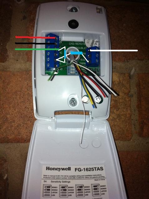
I *believe* my kit's installed using "Always Closed, with EOL", can anyone verify/confirm from these images?

All being well I'll be adding a few more sensors tomorrow and want to know I'm wiring it up right.

pirzo.jpg

pir1k.jpg


From the weekends research, I've read that installing Resisters should always be done at the last device, and that installing res's in the panel is a bad idea. My door contact has it's resistors in the panel. I'm presuming this is due to size etc and is not actually an issue (it works!).
 
Wrong from the looks of things, Should be two resistors for a start.

1 leg in zone, with one leg of resistor.
Next zone terminal with twisted pair of resistors.
Next (3rd leg) of resistors in tamper.
Last wire in the last tamper terminal
 
looks like he needs new glasses if he can see the other resistor behind the wires
 
Nope, just needed to put them on.
As its so untidy there, and its still wrong.
 
There's 2 resistors in there. One is linking 3&4, the other 4&6 I think. Awkward PIR to get into so might not be correct.
 
As Alarm here. also, resistors must not be wired in the panel, contacts are tight i know, but it can and is done with no problems

Also vini, the terminal strip on that pir can be removed (helps with wiring)
 
Ok, starting simple, the door contact and I'm struggling to grasp EOL (I think!)

This is what I currently have;

doorc.jpg


The panel is telling my I have tamper on the contact. The resistors are 1k.


Then there's the Glass Break sensor;

phototpe.jpg


V+ & V- are fine, they're my green & white
NC & C I presume are A & B / 1 & 2 (zone) so my red & blue

the rest, I don't know what goes where, any clues? Where would the resistors lie?
 
Your door contact is right. Bet its a pressure fault. Think of the break glass as your door contact. The silver screws are the C/NC and you should connect the tampers..... Or if you got the PIR working, the BG is the same in essence.

Galaxys should be left to the pro's though, grasping fsl/eol is not as easy as it first appears eh :?:
 
We're almost there! I've got the door contact working now, was user error! I'd overlooked the fact there's 6 connection points in the panel for 4 zones! Now I have the door contact linked into the 0v with the previous zone all is well!

I think I'm struggling with a similar problem with the Glass Break, I have it wired like this; but getting tamper when trying to exit engineer mode. I've wired the panel like this (is the fact theirs no crossover on 0v my issue?)

This is my last issue, any help would be massively appreciated!
 
Your wiring looks correct.
What you may have missed is that you need to "spare" the unused zones in option 52.
As all zones are programmed as used from the start up.
 

DIYnot Local

Staff member

If you need to find a tradesperson to get your job done, please try our local search below, or if you are doing it yourself you can find suppliers local to you.

Select the supplier or trade you require, enter your location to begin your search.


Are you a trade or supplier? You can create your listing free at DIYnot Local

 
Sponsored Links
Back
Top