PLEASE NOTE (Thanks to SecureSpark)
Before changing a light fitting or switch (or any other accessory for that matter), please do what you can to document the existing connections to that equipment. Take photo's and write down which wires are connected to which terminals on the accessory or light fitting.
Especially, do NOT assume blue (or black) -sheathed conductors are neutrals!
A classic DIY mistake is to take down a correctly connected light fitting with more than one cable connected to it then wire up the new one with all browns (reds) to the live terminal and all blues (blacks) to the neutral (Not forgetting the earth terminal to the cpc's, where present).
When the circuit is re-energised, it is discovered that the light is on with the switch(es) in the "OFF" position(s). When the (one) switch is switched to the other position, the circuit protective device opens, as there is now a short circuit between live and neutral.
Additionally, there may well be three core cables connected to extractor fans etc... Do not assume certain colours must be lives and others neutrals.
Also, this sounds a little obvious, but if the wiring is not faulty and the accessory or light fitting is working, please ensure it is reconnected in the same manner as before.
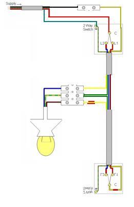
1) SINGLE WAY LIGHT VIA A JUNCTION BOX

Click image to enlarge
NOTE-
If a metal light switch is used, connect the earth wire to the earth terminal on the light switch and loop to the back box.
Using a switch wire with twin red + earth:

(Click on image to open)
Harmonized (Brown / Blue):

(Click on image to open)
Harmonized with twin brown + earth switch wire:

(Click on image to open)
Before changing a light fitting or switch (or any other accessory for that matter), please do what you can to document the existing connections to that equipment. Take photo's and write down which wires are connected to which terminals on the accessory or light fitting.
Especially, do NOT assume blue (or black) -sheathed conductors are neutrals!
A classic DIY mistake is to take down a correctly connected light fitting with more than one cable connected to it then wire up the new one with all browns (reds) to the live terminal and all blues (blacks) to the neutral (Not forgetting the earth terminal to the cpc's, where present).
When the circuit is re-energised, it is discovered that the light is on with the switch(es) in the "OFF" position(s). When the (one) switch is switched to the other position, the circuit protective device opens, as there is now a short circuit between live and neutral.
Additionally, there may well be three core cables connected to extractor fans etc... Do not assume certain colours must be lives and others neutrals.
Also, this sounds a little obvious, but if the wiring is not faulty and the accessory or light fitting is working, please ensure it is reconnected in the same manner as before.
1) SINGLE WAY LIGHT VIA A JUNCTION BOX

Click image to enlarge
NOTE-
If a metal light switch is used, connect the earth wire to the earth terminal on the light switch and loop to the back box.
Using a switch wire with twin red + earth:

(Click on image to open)
Harmonized (Brown / Blue):

(Click on image to open)
Harmonized with twin brown + earth switch wire:

(Click on image to open)


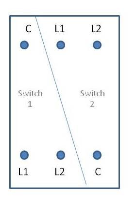
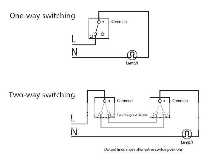
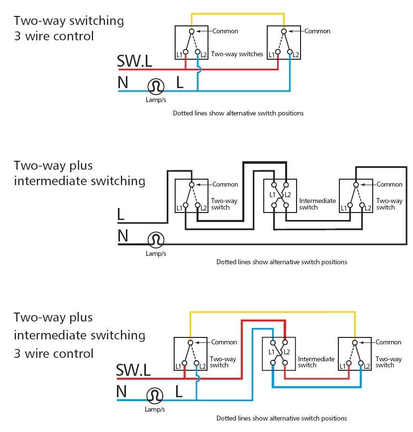
 on't be confused if a different colour goes to a different terminal. Often Red is used as "Common" & Blue & Yellow as strappers (L1 & L2).