here's a good one for you!!!!!

Then unions if they come with the pump (ask) should be 11/2", so make the connection in 42mm copper.

Now I hate to be a party pooper but I think your wasting your time, have you turned the original pump to its lowest setting, There's a jack plug that you turn to different positions, and you can see the setting through the spy glass.
 
Sponsored Links
PTH said:
If you have a sealed loop of pipework which is, for arguments sake 10m from it's lowest to it's highest point then the static gauge pressure at the top will be zero and at the bottom will be roughly 1 bar (please, nobody start being all pedantic about gravity and relative water densities).

If you add an expansion vessel at the top of the system and push in 0.5 bar of air the entire system pressure is raised by that value ie the gauge at thee top will now read 0.5 bar and the one at the bottom will read 1.5.
If you now move the expansion vessel to the bottom of the circuit exactly the same pressures will be found throughout the system.

This is all before any pumps start.

The question is, what does happen when the pump starts?

Consider a level loop of pipe, rads, boiler, pump, etc. From this, you have a tee with a vertical pipe rising 10m and a pressure gauge adjacent to the tee. You fill it to the top, no air left in it. Innit. Pump off, you get 1 bar on the gauge ( 98.1 kPa for pedants) and 1 bar all around the circuit, because it is horizontal.

You start the pump. Does the gauge pressure rise, fall or stay the same?

If you think the pressure rises, then the water level in the pipe must rise (H = P/ rho. g and all that). Where would the extra water come from? The loop is full, it can't suck in air, the water doesn't expand.

Same problem, but with the tee and gauge upstream of the pump inlet. You get 1 bar static pressure with the pump off. When you start the pump does the gauge pressure rise, fall or stay the same?

If you think it falls, then the water level in the vertical pipe must fall, so where would the water go to? The loop and vertical pipe are full. Water is incompressible (practically incompressible for pedants, please belt up about bulk modulus), so it does not squash up.


In both cases, it stays the same; same with a F&E tank instead of a vertical pipe, same with a diaphragm expansion vessel.

Which raises interesting questions about how the pressure changes around the circuit when the pump starts.
 
With a pump of that size you should expect a pressure difference up to 1bar across the pump.
 
image001-4.gif
 
Sponsored Links
DOITALL:
the pump is set to the lowest speed No1 as seen thru the spy hole, this pump used to run 2 x 53Kw boilers in tandem, it is now only running one boiler of 53Kw which is big enough for the whole house. Grundfos tell me that the correct size pump should be the UPS 32-55 giving 1.15L/s and the pump now gives 2.7L/s.

New pump is on order but not paid for yet so I could change my mind.
 
Well I think there's too much technical bullsh*t and not enough lateral thinking.

You say its a sealed system, what pressure is it, push it up to 1.5 bar.
Check all the motorised valves are open, and get the air out of the return.

And forget about all the rubbish connected with the size of the boilers. A pump shifting water at 75c does'nt give too hoots where it comes from.

And on that note have you restricted the supply to the pump by removing one of the boilers, a photo of how they were connected and or a drawing of the plant room.
 
OK go here to see pics of the boilers and pipework hope it helps
http://www.flickr.com/photos/57681709@N00/?saved=1

doitall:

Yes i think the flow to the pump has been restricted by disconnecting one boiler, the pump was fed with 2 x 1.5" bsp and is now fed with 1 x 1"bsp, quick advise would be appreciated as the new pump will be ready for collection tomorrow
 
Pump is being starved of water.

The boiler need more flow so either re-connect the other boiler or re-pipe the one that is still connected
 
doitall said:
Well I think there's too much technical bullsh*t and not enough lateral thinking.

Not enough joined-up, technical thinking.
The system is at 1.2 bar at the pump outlet, about 0.2 bar at the inlet and it sounds like it might be cavitating? Well, what a surprise! Just disconnect the expansion vessel and connect it upstream of the pump to any convenient fitting, refill and see if that improves things. If it works, it's cheap. If it doesn't work you can spend your money on something else.

Never mind buying new pumps, there's better ways to pipe those things up; save your euros for that.

Any Y-pattern strainers on the pump inlet? How about a sketch of the system? The pictures don't reveal much.

doitall said:
And on that note have you restricted the supply to the pump by removing one of the boilers.........

I doubt that would make much difference. They look like CI boilers which usually had a negligible resistance, compared to the resistance of the rest of the system.
 
But it will make a difference onetap, the pump wants 2.7 l/m, it isn't gonna get it from that 1" pipe, and thats not counting the turbulence from those bends.
 
As Onetap says, move the neutral point (expansion vessel connection) just upstream of pump and the pump inlet pressure will then be high enough (with sufficient pressurisation) to prevent cavitation.

Over sized pump may result in excessively high flow velocity, but this can be reduced by adding to circuit resistance downstream of pump (e.g. closing down valves) and/or fitting a by-pass to accommodate excess flow.
 
I agree with Onetap. I have never seen a Combination boiler that doesn't have the expansion vessel on the upstream side of the pump.

Pumps that don't self prime require pushing. Always treat an expansion vessel as you would a cold feed.

Sorry BelgiumBoy but not a lot of assistance to your problem.

Stan
 
Chrishutt said
As Onetap says, move the neutral point (expansion vessel connection) just upstream of pump and the pump inlet pressure will then be high enough (with sufficient pressurisation) to prevent cavitation.

I am in agreement with Doitall. He certainly seems to know what he is talking about.
Moving the expansion vessel upstream of the pump will not cause the pump inlet pressure to increase.
Can you explain how this will be the case ?.

You are simply giving the pump an accumulator to push water inside causing a cushion.
Hydraulic systems in excavators have set ups like these to absorb shock and protect the pump when extreme forces are exerted upon the rams.
As for increasing pressure on the inlet side you are in cloud cuckoo land if you think this will happen.
 
Sider said:
Can you explain how this will be the case ?.
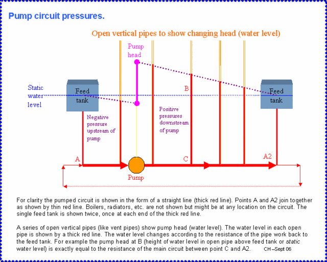
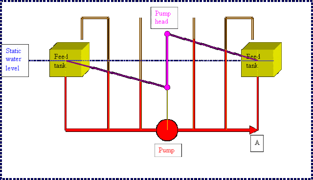
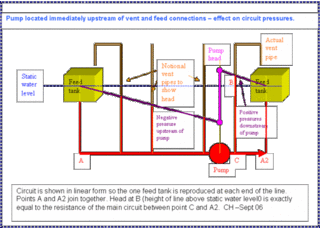
If you refer to the diagram I posted above, you will see that the extent to which the pump head raises or lowers pressure in relation to the static pressure depends on the pump position in relation to the neutral point (in this case the expansion vessel connection, but shown as the F&E tank in the diagrams).

If the neutral point is immediately upstream of the pump, all circuit pressures will be raised above static level by the pump except the very short section between neutral point and pump inlet, where pressure will be lowered. However because this is such a short distance the lowering of pressure below static will be very slight.

On the other hand if the neutral point is immediately downstream of the pump, all circuit pressures will be lowered below static level by the pump except the very short section between neutral point and pump outlet, where pressure will be raised slightly. The depression of static pressure will be highest on the pump inlet.

These diagrams might help illustrate this. The first shows the pump midway from the neutral point, with the pump head equally raising downstream (outlet) pressures and lowering upstream (inlet) pressures. The second shows the pump just upstream of the neutral point, with pump head mostly depressing circuit pressures, especially at the pump inlet.

 
Sorry guys but this is going well over my head now.

Today is offically no heating day in Belgium, (wife will be pleased) going to try and increase the size of the inlet pipework to the pump, this seems the cheapest way before buying a new pump and I got to get the pipework anyway, if this fails to stop the cavitation then as I see it my only other option is to reduce the size of the pump as well, at the same time I'm gonna move the pressure vessel onto the return feed to the boiler. Hope I got all your advise right.

Will keep you updated ASAP

Thanks
 

DIYnot Local

Staff member

If you need to find a tradesperson to get your job done, please try our local search below, or if you are doing it yourself you can find suppliers local to you.

Select the supplier or trade you require, enter your location to begin your search.


Are you a trade or supplier? You can create your listing free at DIYnot Local

 
Sponsored Links
Back
Top