fsl on two contacts

Status
Not open for further replies.
Joined
16 Aug 2012
Messages
642
Reaction score
20
Location
London
Country
United Kingdom
Good Morning all,

Just a bit of reassurance required,

I'm happy when it comes to CC wiring on alarms, but trying FSL for the first time so please be gentle!

Followed various diagrams provided online, and resistors that come with my alarm panel (scantronic 9752)...

I have run wires to multiple windows from the control panel, which will be wired up as one zone... I.e, two contacts, with separate wires running to the control panel (in case i want to split it later), but as one zone now.

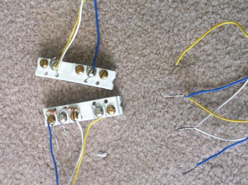
So i did a test wire as attached:

Can someone eye ball it and let me know if it looks ok or have i missed something?

I will check resistance when i actually wire up but going with the resistors provided at present.

Blue and Yellow on the right are for the zone, blue and yellow twisted will be soldered and heat shrunk in the control panel as will the white.

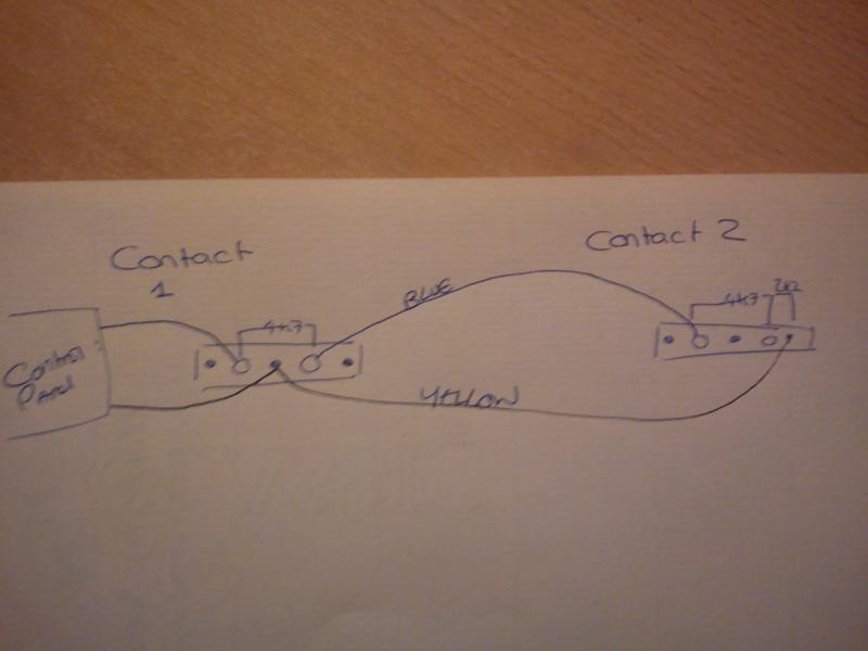
On the top contact, both resistors, blue from zone goes to the 2.2k tamper resistor, output from that to the input for reed, and also to the 4k resistor. the output from the 4k resistor goes back through the white to the control panel, and back to the second contact into the reed OUT for the second contact.
The output for the first contact reed goes via the control panel and into the in for the second reed.

The out for the second reed along with the white returns back to the second connector for the zone on the control panel...

Hopefully the picture makes the above description clearer!

Pic:

I tried to check it with the multimeter i have, but it wont measure anything above 1k ohm so useless. Looking to get a new one later so test this if need be!

Look forward to a response!
 
Sponsored Links
Follow the picture and you'll be ok. its best of you take cable from the first contact to the second when you have two detectors on fsl.


If you want to split it later, then loop through say the red the black wires in the first contact to the second contact, joining in the 1st contact and marking at the control panel end. [/img]
 
Sponsored Links
Thanks josh451.

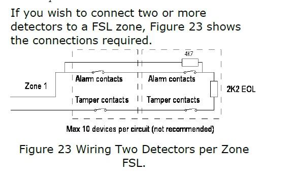
I'm confused between what you have and this which i found in the installation manual for the i-on160EX describing how to do it (and what i followed to some extent):


Am I right in thinking that the 9752 does FSL in a different way to the i-on160EX then?
 
Thanks josh451.

I'm confused between what you have and this which i found in the installation manual for the i-on160EX describing how to do it (and what i followed to some extent):


Am I right in thinking that the 9752 does FSL in a different way to the i-on160EX then?

Well, the diagram shows the 4K7 resistor covering both the alarm contacts, similar to my diagram, but why they have decided to illustrate it the way they have done i haven't got a clue.

But why you are reading the Ion manual when you are installing a 9752...
 
That's what i think ive wired (just via long wires between the contacts).

Basicly i was deciding between the 9752 and 160. Didnt see any extra features that i needed in the 160 so went for the cheaper of the two options - the 9752.

Kept the manual for the 160 for this one diagram of how to wire two contacts as fsl!

How does the 9752 respond when two contacts are open? ie 4.7k from each, which ends up with a 2.2K plus 4.7K plus 4.7K totaling resistance of 11.6K?
Does it understand that two different contacts are opened individually? eg using the chime, if i opened one window, the chime goes off, if i open the next window on the same zone loop, will it chime again?

Your not really understanding how end of line technology works, don't forget that zones are normally closed, going OPEN on alarm. The panel see's both resistors when the zone is closed.

As to your question, when the one door is opened, the panel will chime, but when the second one is opened, the panel won't chime, as the zone is already open. If you closed the 1st door and opened the second, it would chime again. Once a zone has been activated, it can't be activated again until it has been closed (if that makes sense)
 
Thanks,
so FSL/EOL doesnt care what the resistance is, so long as there is a minimum of 2.2k indicating that tamper isn't broken?
(again as part of deciding what unit i looked at the 9751 manual and found the section on masking, indicating 9.1K was masked and anything above that was taken as open circuit tamper alarm)

so for example:
both contacts open, and tamper not broken =
2.2K + 4.7K+4.7K = 11.6K which indicates tamper ok and zone open,

One contact Open and tamper not broken =
2.2K + 4.7K + 0 = 6.8K = tamper ok and zone open

neither contact open, and tamper not broken =
2.2K + 0K + 0K = 2.2K - tamper ok, zone closed.


From what i read on :

http://www.thesecurityinstaller.co.uk/community/topic/3229-scantronic-9651-2x-contacts-on-fsl/

you should use one for tamper and one over the contacts to avoid tamper situation?

I don't understand your last post, so lets keep it simple. Put each contact on its own zone, as you say you've run cable to each sensor. Wire and program them as normal. Job done.
 
ok - based upon the forum linked above, the user was having problems when both contacts are open because the alarm saw too much resistance and thought there was a tamper fault.

Will i get the same with mine if i wire with individual resistors as suggested?
with both contacts open, the total resistance will be approx 11.6K ohms, where as a single contact would see it as 6.9k ohms.

And unfortunately i cant split any more - I'm already using 23 zones by splitting as much as possible over the cp and two expanders. If i split the remaining contacts 1 more expander wont provide enough zones and the panel can only support 3 expanders - 32 zones total!
 
.... then you should have bought a bigger panel

Not sure you can do this on a 9751/2. You can on an i-on and a Galaxy for instance.... as you said the resistance might be too high if both zones open together

If your ***** you can wire the contacts as conventional at the contacts then series them together in the panel, to make one zone, then fit the resistors at the panel end.
 
so for example:
both contacts open, and tamper not broken =
2.2K + 4.7K+4.7K = 11.6K which indicates tamper ok and zone open,

One contact Open and tamper not broken =
2.2K + 4.7K + 0 = 6.8K = tamper ok and zone open

No, re read the manual about EOL. The values your giving are NOT what the panel needs.
 
No, re read the manual about EOL. The values your giving are NOT what the panel needs.

Do you have a list,extract, photo or anthing else i can ref against for the 9752? I cant see onein the manual i have, and at present im having to canibalise info from different manuals...
 
ok - based upon the forum linked above, the user was having problems when both contacts are open because the alarm saw too much resistance and thought there was a tamper fault.

Will i get the same with mine if i wire with individual resistors as suggested?
with both contacts open, the total resistance will be approx 11.6K ohms, where as a single contact would see it as 6.9k ohms.

And unfortunately i cant split any more - I'm already using 23 zones by splitting as much as possible over the cp and two expanders. If i split the remaining contacts 1 more expander wont provide enough zones and the panel can only support 3 expanders - 32 zones total!
The hand drawn diagram is not the same as the schematic from Scanny.
To solve the problem of both doors being open and causing a fault, follow the schematic....or get a bigger panel.
 

DIYnot Local

Staff member

If you need to find a tradesperson to get your job done, please try our local search below, or if you are doing it yourself you can find suppliers local to you.

Select the supplier or trade you require, enter your location to begin your search.


Are you a trade or supplier? You can create your listing free at DIYnot Local

 
Status
Not open for further replies.
Sponsored Links
Back
Top