Yet Another Nest Learning Thermostat Gen 3 HELP!!!

Joined
25 Nov 2018
Messages
6
Reaction score
0
Location
Burton on Trent
Country
United Kingdom
Hi All,

Can you offer me a little help,
Ive brought a Nest Learning Thermostat Gen3 and was hoping to install myself,
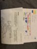
Ive done as much digging as i can with instructions I've got with my current set-up and took as many pics as i think i need....
Just need a bit more help as i can't get it to run.....

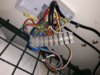
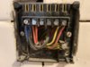
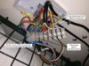
Currently have a S-Plan Layout i think,
Boiler,
2x 2way Valve's (1 for CH / 1 for HW)
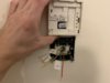
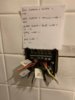
Programmer and Thermostat
Megaflo

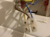
Looking to try keep existing Thermostat Wiring to use with the Nest Display

Can you offer me any help??
 

Attachments

  • Airing Cupboard Wiring Pic.jpeg
    Airing Cupboard Wiring Pic.jpeg
    275.7 KB · Views: 274
  • Airing Cupboard Wiring.jpeg
    Airing Cupboard Wiring.jpeg
    298.2 KB · Views: 263
  • RTS1 Therm.jpeg
    RTS1 Therm.jpeg
    141.8 KB · Views: 282
  • Tempus 6 Pro.jpeg
    Tempus 6 Pro.jpeg
    259.6 KB · Views: 275
  • Tempus 6 Wiring.jpeg
    Tempus 6 Wiring.jpeg
    175.6 KB · Views: 267
  • Wires Behind Tempus 6.jpeg
    Wires Behind Tempus 6.jpeg
    128.9 KB · Views: 262
Sponsored Links
Not entirely I just need to work out which ring is the thermostat to isolate then switch to 12v, problem I had is one of the blue with black sleeves and the one with CH call is going to thermostat. Which I want to use for the nest display,
 
Unfortunately the photos of the wiring don't help that much without knowing what is connected to both ends of each wire. The method of wiring & the wire colours used are variable, depending on the personal preferences of the person that installed it, the layout of your property and the components & cables available.

The room thermostat will be wired in 'series' somewhere in the circuit between terminal 4 of the existing programmer (Heating on) and the live wire to the motorised valve controlling the central heating. There are several ways of doing this, so it can only really be traced by someone physically on site. Only when you have found both ends of the thermostat cable, and tested it electrically to make sure that you have the correct cable and that it is completely disconnected from the 230V wiring can it be used for connecting T1 & T2

After removal of the thermostat cable, you will also have to complete the heating circuit, by bridging the terminals where the live thermostat live switching wires were previously connected. Otherwise the heating wiring will be permanently open circuit and will not come on at all.
 
Sponsored Links
So what I worked out so far is,
On the programmer - one of the Red L wire is permanently live and the other Red L wire is live when connected with each other, I traced it back to the terminal box in the airing cupboard terminal 5 which the CH Red Wire with Red Sleeve is connected to,

Does this help anymore or not really???
 
Not really, wire colours are meaningless generally when it comes to heating systems, as are terminal numbers, all down to the preferences of the original installer.

I assume this is the thermostat, so you need to find the other end of this cable:-

Capture.JPG


So you are looking for a cable with red, yellow, blue and earth wires. Once you think you have found it, it should be tested by someone competent with a multimeter to make sure you have found the right one.

Then disconnect it completely at the other end, after noting where the red and yellow wires came from, then insert a wire link between the terminals that the red (L) and yellow (call) wires have been taken out of. All other wires must remain securely in place.

Once the cable is completely disconected, then you can use it to connect the Nest thermostat to the Heat link. T1 & T2. Although quite often the other end is not where the Heat link is going to be sited.
 
Right so had a bit of spare time to check wiring out, So what ive found is in the image below, So I'm thinking if i link the Red/Red Sleeved wire to the Red Thermostat wire with the Yellow, And move the switched Live Red wire to where the Red/Red sleeved wire currently used for CH it should complete the CH circuit and be able to use the Blue and Red for the 12v of the Nest T1/T2 and put a jumper wire from where the CH is currently placed into where the Yellow thermostat call is??

Or am i Way Off???
 

Attachments

  • image.png
    image.png
    16 KB · Views: 260
Sorry but I cannot see the photo it is too small, and wire colours do not help, unless you say what is connected to each end of each wire. One installer may use a black wire for the switched live, another may use grey another yellow and so on.

I have told you what you need to do. Trace the thermostat cable back to its origin when you have positively identified it and tested it, then...
Then disconnect it completely at the other end, after noting where the red and yellow wires came from, then insert a wire link between the terminals that the red (L) and yellow (call) wires have been taken out of. All other wires must remain securely in place.
 

DIYnot Local

Staff member

If you need to find a tradesperson to get your job done, please try our local search below, or if you are doing it yourself you can find suppliers local to you.

Select the supplier or trade you require, enter your location to begin your search.


Are you a trade or supplier? You can create your listing free at DIYnot Local

 
Sponsored Links
Back
Top