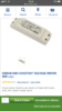
Putting 240 volts into this power supply may have damaged it beyond repair

You are using an out of date browser. It may not display this or other websites correctly.
You should upgrade or use an alternative browser.
You should upgrade or use an alternative browser.
Strip light issue
- Thread starter Jupiter01
- Start date
Sponsored Links
- Joined
- 17 Aug 2010
- Messages
- 2,741
- Reaction score
- 453
- Country

It's odd because they do a 230V version and have a massive comprehensive catalogue intended for Europe. The biggest problems with replacing the driver will be
a) finding a uk supplier of the 230V part, and
b) the totally unrealistic price.
I notice that Toolstation do some led drivers that may even have the same proprietary connector system. ('may' is the operative word - I have no idea).
a) finding a uk supplier of the 230V part, and
b) the totally unrealistic price.
I notice that Toolstation do some led drivers that may even have the same proprietary connector system. ('may' is the operative word - I have no idea).
some led drivers
Being pedantic but the item needed is a power supply that provides a constant DC voltage and NOT an LED driver which would drive a constant current through the LED elements.
Presumably the 120v version is for the continent and other countries supporting the standard. Could there be a use for this in UK residential market?
Can I not replace it with this? The led connection mechanism will just wire into the 24v terminals of this driver?
Can I not replace it with this? The led connection mechanism will just wire into the 24v terminals of this driver?
Attachments
Sponsored Links
- Joined
- 17 Aug 2010
- Messages
- 2,741
- Reaction score
- 453
- Country
That is the definition you have decided to adopt. As it happens Toolstation, who I referred to, call them led drivers. I am agnostic on the subject, but these days it's anybody's guess unless you check what type it is.
- Joined
- 17 Aug 2010
- Messages
- 2,741
- Reaction score
- 453
- Country
No, they all use 230V, the same as we do.Presumably the 120v version is for the continent ...
Could be fine. Just can't see if it has a minimum current.Can I not replace it with this? The led connection mechanism will just wire into the 24v terminals of this driver?
Presumably the 120v version is for the continent
For the USA and Canada
The item you posted will be OK for the lamps as it is 24 volt DC. Take care to get the polarity correct.
I am agnostic on the subject,
I would like to be "agnostic" but seeing the damage that occurs when a constant current driver is used instead a constant voltage supply makes it hard to ignore the problem.
- Joined
- 17 Aug 2010
- Messages
- 2,741
- Reaction score
- 453
- Country
If you said 'constant current supply' versus 'constant voltage supply' then I would agree. But you can't insist of your definition of 'driver' being universally used. And it isn't. To be helpful you have to use the terms 'constant voltage' or 'constant current'. Nothing else is unambiguous.
Thanks guys. There’s no mention of minimum current in here:
https://www.screwfix.com/p/osram-240v-constant-voltage-driver-30w/4725x
Just a couple of questions I wanted to clear up please:
1. Will this 24v adapter take care of the 3 strip lights that are connected together? Does this still equate to 24v?
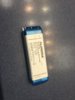
2. The other light (currently working) also has the same driver (power supply?) I.e. 120v input but is still working. Is this expected and should I replace this too?
3. Also, why is the continuity light activated on my 2 pole tester when I apply probes to these two terminals and the switch is In the off state? I thought continuity is when I have a probe on either end of the same wire. That shouldn’t be the case when I am touching one of the probes on live and another on negative?
https://www.screwfix.com/p/osram-240v-constant-voltage-driver-30w/4725x
Just a couple of questions I wanted to clear up please:
1. Will this 24v adapter take care of the 3 strip lights that are connected together? Does this still equate to 24v?
2. The other light (currently working) also has the same driver (power supply?) I.e. 120v input but is still working. Is this expected and should I replace this too?
3. Also, why is the continuity light activated on my 2 pole tester when I apply probes to these two terminals and the switch is In the off state? I thought continuity is when I have a probe on either end of the same wire. That shouldn’t be the case when I am touching one of the probes on live and another on negative?
- Joined
- 17 Aug 2010
- Messages
- 2,741
- Reaction score
- 453
- Country
1. The power supply/driver is for 30W. So that's how much power it will supply. If the 3 strips add up to more then you would have a problem (though you could choose a higher wattage part).
2. It may or may not have a reduced lifetime - it depends on the design. I would expect it to have a shorter lifetime or they would have specified a wider mains voltage range like 100 - 250V ac.
3. Your test instrument doesn't know what you have probed. If the current that flows between its terminals exceeds a certain value it will indicate continuity. Your would need to have the circuit diagrams of both the tester and the faulty circuit (with fault simulated) to be able to explain why it exceeds that current.
(Also live relates to ac and negative to dc - so the question is unclear)
The total wattage of the 3 lights does not exceed 30W. I was asking about the 24 volt requirement and checking that the three lights in total don’t exceed this?1. The power supply/driver is for 30W. So that's how much power it will supply. If the 3 strips add up to more then you would have a problem (though you could choose a higher wattage part).
“Negative” should have read “Neutral”. Sorry.(Also live relates to ac and negative to dc - so the question is unclear)
Also, can you please elaborate on #3. Why would there be any current flowing between these terminals when the switch is not on?
Thanks for your guidance. This has been very informative
- Joined
- 17 Aug 2010
- Messages
- 2,741
- Reaction score
- 453
- Country
The 24 volts would be applied to each of the strips in parallel, so each strip would be driven by 24V. So everything would be fine. It's similar to the sockets in your house all being in parallel so you see the same voltage at each socket.The total wattage of the 3 lights does not exceed 30W. I was asking about the 24 volt requirement and checking that the three lights in total don’t exceed this?
Also, can you please elaborate on #3. Why would there be any current flowing between these terminals when the switch is not on?
The current flows because a continuity meter is trying to measure resistance. To do this it applies a small voltage and measures the current resulting from it. Then it calculates resistance = voltage / current.
If this value is less than a certain (manufacturer set) value it assumes 'continuity', and buzzes (or whatever). If the Power Supply is broken, it is anybody's guess whether sufficient current would flow. (Actually the same applies even if not broken.)
would be an issue if the voltage on the DC was higher than 24? Let’s say 75?
Deceased LED lamps would be the issue.
DIYnot Local
Staff member
If you need to find a tradesperson to get your job done, please try our local search below, or if you are doing it yourself you can find suppliers local to you.
Select the supplier or trade you require, enter your location to begin your search.
Please select a service and enter a location to continue...
Are you a trade or supplier? You can create your listing free at DIYnot Local
Sponsored Links