Wiring the power board of a treadmill

Joined
15 Jun 2020
Messages
3
Reaction score
0
Country
Libyan Arab Jamahiriya
Hello...

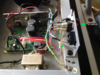
I'm not a technician and I don't know much about electronics. I am trying to fix our treadmill.
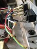
It seems all it needed a new power socket. I have installed a new power socket but I don't know how to attach the different wires to its three pins. As you can see in the picture, the three wires I want to attach to the power socket, are blue, white and red (attached together). I don't know why the red and white are attached together. Properly, the person who tried to fix it a while ago.
Could you please help answer my questions:
Which wire should be attached to which pin of the power socket?
How I am going to attach them? Do I solder them directly to the pins?

( * Please excuse the dirt and dust in the picture as the machine has been sitting for a long time collecting dust. )
 

Attachments

  • treadmill.png
    treadmill.png
    3 MB · Views: 410
  • IMG_7746.JPG
    IMG_7746.JPG
    386.4 KB · Views: 436
Sponsored Links
Is the black part that is alongside the switch but has no wires connected to it, what you are calling the power socket?
If so, did you not make a note of what wires were connected and how before removing the old one?
 
I was not the one who disconnected the wires. I found the situation as it is. Yes, I meant the power socket connector ( the piece where you connect the cable -Please see the first picture- ).
I need help to connect those three wires to the pins of the power socket connector
HTB1r0JrbRfM8KJjSZFrq6xSdXXav.jpg
IMG_7751.JPG
IMG_7750.JPG
. I'd be grateful if you tell me how to connect these three wires to the pins. I've included more pictures to clarify the situation.
 
I'm afraid I have no idea. But assuming you bought the socket from the manufacturer, can't they tell you?
Other wise, the pin marked E must be connected to the chassis, it's the earth.
What is that next to the switch? Is it a fuse or a light?

I guess the pin marked L should be connected to the switch, but whether that's the blue or the red is anyone's guess.
I'd guess the red should be connected to the pin marked L.
That leaves the question of which wire is the neutral, you need one at the switch for the light to work. Therefore I would guess the blue from the switch should be connected to the pin marked N.

That leaves the white. I would guess that is the main neutral from the machine, and should also be connected to the pin marked N.

BUT, I'M only guessing and I have no experience of this or any other electrics.

Bear in mind, you have no idea what the previous owner did, or if they rearranged any wiring.

Normally, one would expect either brown and blue, or red and black to be connected to the rear of the power socket.
 
Sponsored Links
I would say :

the Blue is the Live from the socket Live to the switch contact
the White is Neutral from the socket Neutral to the PCB
the Red is also Neutral from the socket to the indicator lamp in the switch.

There needs to be a Green/Yellow from the socket Earth to the chassis at "0" ( next to the "8" and existing Green/Yellow )

The item next to the switch is almost certainly a fuse or ( resetable thermal cutout ) in the Live ( Blue) wire.
 
Salwa,
it scares me for you to fix this machine as you do not have the ability to test for safety.
And you do not know how and why it failed before.

My immediate alarm bell is that there is no ground (and the ground cable is missing) between the cable socket and the chassis.

Sorry to be less than helpful, but I do suggest that you need someone who has: test equipment, a crimping tool, a length of earth cable, and insulated spade/ring connectors to assist.
If you have this, I would be more happy to tell you which cable is which and where to connect.
But without this there is a significant chance you will electrocute someone who uses this equipment.
SFK
 
Bernard beat me to it :>
Bernard, that is also how I saw the cables being connected.
>> Blue cable is Live and goes to the "L" on the new socket
>> White/Red cable are both Neutral and both go to the "N" on the new socket (the thin red wire provides Neutral to the bulb in the switch).
>> It is critically missing a green/yellow Ground cable that goes from the from (marked 'O') to the Middle pin marked "E" on the new socket.

As Bernard says, "There needs to be a Green/Yellow from the socket Earth to the chassis".
I also see this as being critical and I feel that this has to be PROPERLY tested to ensure connection is good.

SFK
 
Last edited:
I largely agree with Bernard.

The Blue is the Line connection from the socket connection marked “L” to the middle switch contact.
(However, what is the object that is now connected to the end of the Blue wire? It needs to be removed.)

The White is Neutral from the socket Neutral (marked "N") to the PCB

The “Red” wire, and its connector, seem to be an extraneous addition and is unnecessary. (The gauge of that wire is smaller than than the other "original" wires.)

(The switch seems to be a Single Pole Double Throw, but only a Single Pole Single Pole switch is necessary. [i.e. There is no need for a connection to the top contact.])

There is a “hole” marked “0”, which seems to be the place where a screw and connector was installed for the Green/Yellow connection to the Earth connection of the Socket.
A connecter and screw similar to that at the position marked “8” should be utilised for that connection.
 
Frodo
The “Red” wire, and its connector, seem to be an extraneous addition and is unnecessary. (The gauge of that wire is smaller than than the other "original" wires.)
That “Red” wire is needed as it provides Neutral to the bulb inside the switch, such that the bulb is illuminated when the switch is in the on position.

As an aside, it is hurting my head that they used Blue as Live and Red/White as Neutral.
SFK
 
Last edited:
Am I correct in saying that if the neutral, from the socket is connected to the switch, so that it is the neutral that is switched, the machine will be permanently live, even though it appears to be switched off?
 
The “Red” wire, and its connector, seem to be an extraneous addition and is unnecessary. (The gauge of that wire is smaller than than the other "original" wires.)
Added because the previous owner did not have a spade connector or crimping pliers?
 
Bobby,
The red wire is necessary as it provides a Neutral to the bulb in the switch (and hence only needs to be thin wire).

I presumed the strange 'metal pin' on the end of the red/white Neutral wire was a pin that had been ripped out of the original socket as the OP stated they had fitted a "new power socket".

SFK
 
Last edited:
The red wire is necessary as it provides a Neutral to the bulb in the switch (and hence only needs to be thin wire).

I presumed the strange 'metal pin' on the end of the red/white Neutral wire was a pin that had been ripped out of the original socket as the OP stated they had fitted a "new power socket".
So the switch is NOT a SPDT but it is a SPST switch with an "indicator" lamp.

(Not easy to see when one has only a rear/side view to go on !)
 
Sponsored Links
Back
Top