Opening between two type of wall - What lintel solution?

Joined
23 Jul 2020
Messages
7
Reaction score
0
Country
United Kingdom
Hi all, I have a basic issue to overcome on a small single storey extension. In a nutshell, the two nibs either side of the 4.0m opening for a new bifold are two different wall types.

There is a nib in 300mm (100/100/100) cavity wall one side and a nib in original 9inch sold brick the other.

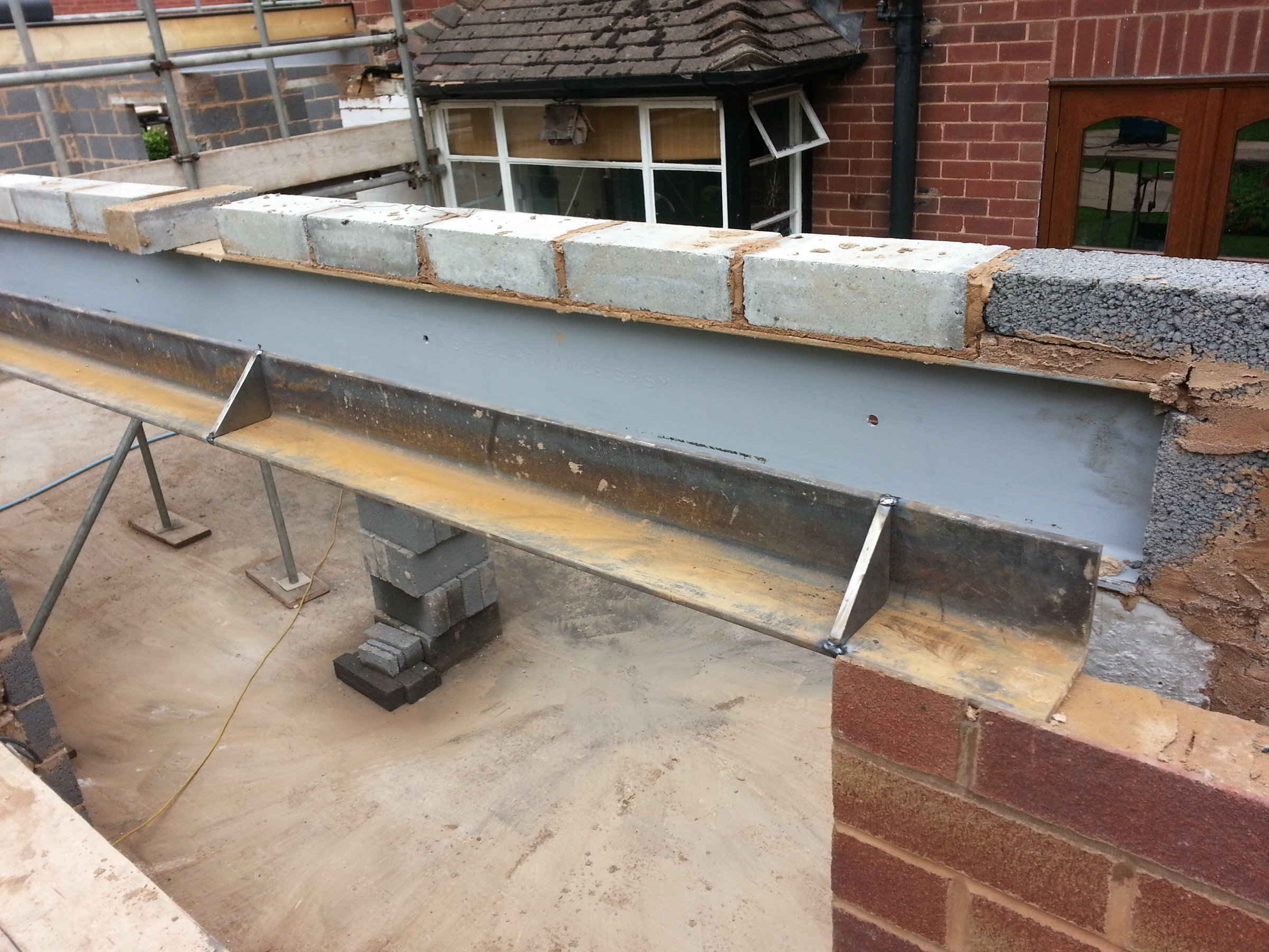
Originally the plans showed a keystone cavity lintel (i think a XCFS/K90) spanning the 4.0m opening. Thats not possible as there are two wall types.

So, after a very short discussion with the builder, it was suggested to put a padstone over the cavity wall, put a keystone IB/K3C solid wall lintel over the span and then have a solider course and 2/3 courses of solid wall above. The rafters for the warm flat roof are then on top of that. The small solid wall above the lintel will be then insulated to regs standard. All sounds fine...

The spec of the lintel is well OTT so no issue there but the thermal bridge over the cavity isn't allowed normally..

Let me know what you all think and if you think you can help? or would propose a different solution.
Thanks again for your time.
 
Sponsored Links
The padstone is bridging the cavity, creating a thermal bridge and is not loading the cavity wall below as it should. What does the designer/engineer/inspector say about this?
 
You don't need a padstone for that span and loading (a few course of brick and a roof?). Besides, a padstone showing on the outside brickwork would look naff.

Bridge the cavity with a piece of steel plate 200 x 250 wide x 4mm thick.
2020-07-23_215822.jpg
 
Thanks Tony, I am going to try and get this through, but BCO maybe hard. I am talking with the engineer later if he calls me back, the engineer was proposing what i saw as a complicated new solution by putting a standard RSJ across the brick face on the cavity to the brick face on the solid wall, bearing 150 either side but then run a long rsj from the inner cavity to the wall perpendicular. to the other solid wall (see attached)

The new beams are in green. I MUCH prefer the solution you have proposed!
 

Attachments

  • BLOCK plan new beams.pdf
    69 KB · Views: 335
Sponsored Links
The scheme your SE has put forward cannot be faulted insofar as it is a 'correct', text-book case of how to solve the problem; will it work? - yes, most certainly, but at what cost?
The metal plate suggestion would work in principle, subject to a suitable thickness, but you could bet the farm that the inspector will not accept it without justification. The problem is therefore one of proof, which would be very difficult.

The issue is the potential slight upward bend in the plate where it passes over the corner of the inner skin, which is difficult to evaluate, and which will put increased localized stress on the corner of the block. There are equations for evaluating the curvature in cases like this, but they are complex and most SEs would have better things to do with their time!

Stop press: thinking around this problem, a short length of steel channel (100mm x 50mm cross-section) might be better. Cut away the two flanges at one end to leave just the web bearing on the outer skin, and with a disc cutter saw two slots in the top of the inner skin block, 50mm deep x 8-10mm wide.
Set the channel down on some stiff mortar; this can then act as a steel padstone. There will be some cold bridging which will have to be addressed, and your SE would need to calculate the bearing stress on the inner skin, taking into account the contact area (he will know the loading at the end of the beam so it's a simple computation). If the figures work, it will satisfy building control's checking engineer (the inspector won't check it himself - he'll pass it over to their SE to check).

Worth considering?
2020-07-24_173156.jpg
 
Last edited:
Great solution, don't think the engineer wants to entertain anything but text book... The builder now suggests to knock down the 9inch solid, and put another few meters of foundation and new cavity... bah!!!! and what a bloody mess that is going to be at this point...

This is the only steel in the whole project...

Attached in the original drawing with the cavity lintel, i believe a K90.... NB there is only 4 courses of face brick above the lintel in the final drawing as there was a height issues (eves had to be 3.0m for PD, but it was done to the lower eve height, not the roof face) I really can't see how either wouldn't be ok.. a 4mm 316 stainless plate bridging the cavity is such a neat solution, the other, also a great solution, and that wouldn't budge..... ... I now need to find an engineer to do me a calc so I can wave it at BCO.... I could stand the Eiffel tower on top of this extension even with a solid wall catnic lintel!

Any suggestions for engineers for me to commission to do me a formal spec?
 

Attachments

  • Screenshot 2020-07-24 at 19.08.43.png
    Screenshot 2020-07-24 at 19.08.43.png
    199.8 KB · Views: 270
OK, use a handsaw instead?
I ended up getting creative with the grinder when building over this angle iron (with steel cleats), as I didnt want an overly large bed joint showing when tring to encorporate the the thick steel and slight warping....


If you look closely youll see I have sunk the angle into the bricks by 10mm. It worked better for the bi-folds that way (having it sitting lower).
 
Last edited:
I ended up getting creative with the grinder when building over this angle iron (with steel cleats), as I didnt want an overly large bed joint showing when tring to encorporate the the thick steel and slight warping....

I don't care what they say about you Noseall, you are good at your job. (y) :ROFLMAO::ROFLMAO::ROFLMAO:

Andy
 
Been moved by the responses to this conundrum by Tony and Noseall, that's a tidy job, wish our bricky was as diligent... its like trying to bath a cat dealing with him and the SE. I like Tony's latest sketch as it means no messing... The final call on the matter will be the BCO. However if now render the two nibs with 100mm external kingspan, its going to have u values that will meet the 2030 regs! I don't want the render the lot, after trying for weeks to match the bricks! But the two rendered nibs won't look so bad... In other news, is it ok to lay 440 block on its side to increase the height of 215 solid wall? I thought we were just going to use bricks, but he says if we are rendering, he'll just use spare block on its side to make up the level to the rafter?
 
The final call on the matter will be the BCO.

Don't defer to the BCO too much; his job is simply to ensure that what you build - or propose to build - complies with the Building Regulations. It isn't a case of presenting a number of solutions, and then asking the inspector to choose one. The correct approach is to decide how you want to do it and, if the inspector is doubtful, to show him how it would comply with the Regulations, in which case he would have to accept it.

In your particular case of supporting the beam across the cavity, I would think that the easiest and cheapest way would be to build a solid return up to the inner face of the outer skin.
Obviously, this would fall below the required U-value for walls - but - you are allowed to trade off areas of walls or roofs which are slightly below standard, by incorporating additional insulation elsewhere in the extension (it's known as the 'area-weighted U-value method' and is described in Part L).

Aside from this, it would be a pretty dull and unimaginative inspector who objected to that slightly-lesser U-value, when you already have a far larger area of 225mm solid wall!
 

DIYnot Local

Staff member

If you need to find a tradesperson to get your job done, please try our local search below, or if you are doing it yourself you can find suppliers local to you.

Select the supplier or trade you require, enter your location to begin your search.


Are you a trade or supplier? You can create your listing free at DIYnot Local

 
Sponsored Links
Back
Top