Timer board

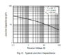
Indeed, they oddly only give Cj (at 1 MHz). Cp which is the parallel capacitance is not given - I guess because at one test frequency it means very little in terms of spec point. I'll stick one on the impedance analyser

The crucial point is 1N4001-4 is usually PN structure and 5-7 is PIN which gives rise to this change.
 
Sponsored Links
Where you care about the parasitic capacitance. The capacitance is usually quite different for a 1N4001 than a 1N4007, so you'll find a it starts to pass more and more high frequency content with no rectifying action.
Fair enough, but I have to say that I was not thinking of (or contemplating using such a diode in) situations in which the (very small) capacitances would be of any consequence. In any event ...
First datasheet on google shows only with a test frequency of 1 MHz, but you get the idea.
Interesting - the first one which I found on Google showed only one curve (which looks as if it corresponds roughly with your one for 1N4001-1N4004) for the entire 1N4001-1N4007 range (as with yours, only for 1 MHz) - hence my comment about the characteristics appearing to be identical for all PIVs ...

upload_2021-5-12_21-52-33.png


... but, as an aside, I'm wondering ... why would the capacitance be particularly dependent upon frequency??

Kind Regards, John
 

Attachments

  • upload_2021-5-12_21-54-26.png
    upload_2021-5-12_21-54-26.png
    20.9 KB · Views: 33
... but, as an aside, I'm wondering ... why would the capacitance be particularly dependent upon frequency??
Kind Regards, John

Not the capacitance itself, but the apparent capacitance measured at the terminals. The model has inductive and resistive elements which give the variance with frequency.
 
Quick test on the LCR meter of the parallel capacitance:
100 Hz:
upload_2021-5-13_9-43-6.png


100 kHz:
upload_2021-5-13_9-42-40.png
 
Sponsored Links
Not the capacitance itself, but the apparent capacitance measured at the terminals. The model has inductive and resistive elements which give the variance with frequency.
Quick test on the LCR meter of the parallel capacitance: .... 100 Hz: .... 100 kHz: ....
Thanks. What is that displaying - do I take it that it is the 'net reactance' - i.e. if the inductive component exceeded the capacitive, it would display a {'net'} inductance, rather than a capacitance ?

If so, I am struggling to understand the figures. If we assume that the inductive component is fairly negligible at 100 Hz, then the 'true capacitance' is presumably around 407 pF, which at 100 kHz would have a reactance of around 3.91 kΩ. However, if I understand correctly, you appear to have measured a net capacitive reactance of 11.6 kΩ at 100 kHz. Were an inductive component having a significant impact at the higher frequency, one would surely expect the net capacitive reactance to be less at 100 kHz then at 100 Hz, not three times greater?

I must be misunderstanding or missing something. Can you help me understand?

Kind Regards, John
 

DIYnot Local

Staff member

If you need to find a tradesperson to get your job done, please try our local search below, or if you are doing it yourself you can find suppliers local to you.

Select the supplier or trade you require, enter your location to begin your search.


Are you a trade or supplier? You can create your listing free at DIYnot Local

 
Back
Top