
You are using an out of date browser. It may not display this or other websites correctly.
You should upgrade or use an alternative browser.
You should upgrade or use an alternative browser.
Vaillant 424 open vent ,pump over run.
- Thread starter bob1956
- Start date

Sponsored Links
Sponsored Links
Yes sorry you are correct,my bad I have connected as you rightly say4 is HW OFF
6 is HW ON
So if you have done it like you say they are the wrong way round.
So 3 on the nest should go to the white on the 3 port valve.
4 on the nest to the grey on the valve and satisfied on the cylinder stat.
6 on the nest to common on the cylinder stat.
That just leaves the orange on the valve and call on the cylinder stat, which should both be connected to the 240 volt RT terminal on the boiler.
4 on the nest to the grey on the valve and satisfied on the cylinder stat.
6 on the nest to common on the cylinder stat.
That just leaves the orange on the valve and call on the cylinder stat, which should both be connected to the 240 volt RT terminal on the boiler.
Ok Iv run the cable in as you pointed out ,my head is fried now just to clarify the orange wire connects to 240v or the RT, on the boilerSo 3 on the nest should go to the white on the 3 port valve.
4 on the nest to the grey on the valve and satisfied on the cylinder stat.
6 on the nest to common on the cylinder stat.
That just leaves the orange on the valve and call on the cylinder stat, which should both be connected to the 240 volt RT terminal on the boiler.
And thanks for your help
The orange wires from motor valves apply 240v to the orange wire when the valve is open which creates a "call for heat" which is then connected to the appropriate 240v call for heat terminal on the boiler.
Apparently the RT in this case.
One has to be very careful because modern boilers can either accept ( old fashioned ) 240v signals or low voltage 24v inputs. And they must be connected correctly or you risk damaging the ( expensive ) boiler PCBs.
Apparently the RT in this case.
One has to be very careful because modern boilers can either accept ( old fashioned ) 240v signals or low voltage 24v inputs. And they must be connected correctly or you risk damaging the ( expensive ) boiler PCBs.
Yes sorry you are correct,my bad I have connected as you rightly say
The orange from the valve and the call from the cylinder stat connect to the RT terminal on the X1 plug on the boiler.Ok Iv run the cable in as you pointed out ,my head is fried now just to clarify the orange wire connects to 240v or the RT, on the boiler
And thanks for your help
Thanks Agile can you clarify which wire goes where(see attachment) as I dont want to damage the boardThe orange wires from motor valves apply 240v to the orange wire when the valve is open which creates a "call for heat" which is then connected to the appropriate 240v call for heat terminal on the boiler.
Apparently the RT in this case.
One has to be very careful because modern boilers can either accept ( old fashioned ) 240v signals or low voltage 24v inputs. And they must be connected correctly or you risk damaging the ( expensive ) boiler PCBs.
Attachments
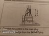
As long as you use the 230V RT side you’ll be fine. The link on the left hand side (24V) that you removed - don’t connect 230VAC to this. I think Agile muddied the water a little.Thanks Agile can you clarify which wire goes where(see attachment) as I dont want to damage the board
So many professionals make mistakes and wrongly apply 240v to low voltage inputs that I do not advise DIYers do get involved in making these connections as the consequences can be so expensive.
To me it is pretty simple as I have a background in electronics. But I have to have a clear head when I do it myself.
I do not think that many manufacturers explain these connections very well. Nor is it terribly difficult to design a circuit to accept 24v that would not be damaged by accidental connection to 240v.
Sometimes I wonder if some manufacturers intentionally make them easily damaged so they can profit from replacement PCBs.
I once went to an interesting talk from a manufacturer on how they try to make their programmers fit other backplates but not allow other programmers to fit their own backplates!
DIYnot Local
Staff member
If you need to find a tradesperson to get your job done, please try our local search below, or if you are doing it yourself you can find suppliers local to you.
Select the supplier or trade you require, enter your location to begin your search.
Please select a service and enter a location to continue...
Are you a trade or supplier? You can create your listing free at DIYnot Local
Sponsored Links
Similar threads
- Replies
- 59
- Views
- 12K
- Replies
- 8
- Views
- 489
- Replies
- 7
- Views
- 3K
- Replies
- 1
- Views
- 909