Softus said:
Onetap said:
If it turns out as a F&R circuit, you need lockshield balancing valves (suitable for very low flow rates) on the return connections at the fittings to balance it, or you won't get any flow to the furthest/least-favoured fittings.
If it's been installed correctly, the circulating pump is the last thing on the return before it connects to the cylinder.
Yes, so the least favoured/ index circuit would probably be the first branch off the flow pipe.
Softus said:
I don't understand your suggestion to use balancing valves - why do you think this is necessary?

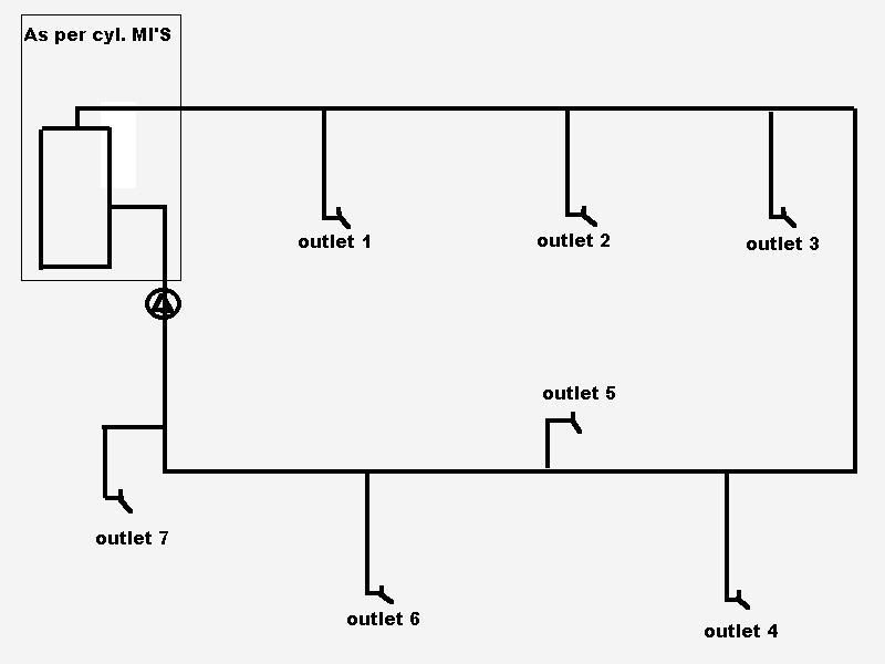
If I may rephrase your question, say the index/least favoured circuit has a resistance of 2,000 Pa at the design flow rate and the most-favoured (nearest the pump) circuit turns out to have a resistance of 100Pa at the design flow rate.
Why do you think water would flow along a circuit with a 2,000 Pa resistance when it can flow along a circuit with a 100Pa resistance?
In reality, it doesn't; the least favoured circuit has negligible flow rate. The most favoured has a huge flow rate, many times in excess of the design. The water tears along the main flow pipe and only flows through those circuits nearest the pumps. You need the balancing valves to add resistance to the circuits nearest the pumps.
It really doesn't work unless you do have some balancing devices. You can use ball/service valves, but the settings are lost the first time they're closed.
In the real world, I worked on a 10+ storey building with a 70 years old plumbing system & big HWS circulating pumps & storage calorifiers/cylinders in the basement. Stop-cocks and gate valves on the HWS F&R pipes, but no lock-shield valves & no balancing. Hot (50 degC+) water at all taps within 60 seconds was needed.
What was happening was that taps on the first floor (which being close to the pumps should be getting lots of flow)
NEVER got above tepid (30 degC+). I waited for 20 minutes with one tap running and it still didn't get hot. On other floors, some were OK, some weren't, it depended on who had been running hot water off. In the basement there was a history of HWS pipe failures caused by erosion due to the excessive water flow rates.
Softus said:
Onetap said:
If the pipes are properly insulated the required flow rate should be the merest trickle. Q is total heat loss from pipes through insulation, dT is (60 -50) deg.
Were you intending to post an equation here?
No. I'm certain that we all know the relevant equation.
Please don't disillusion me.