
Like I said above - albeit indirectly. Is it bed time yet?
yes it is bed time, get some rest and I'll report back on sat!

Like I said above - albeit indirectly
Like I said above - albeit indirectly
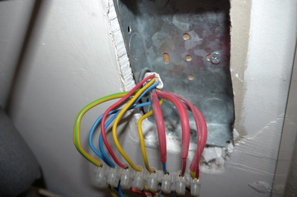
, another couple of hours before bed time.and wheres the other connection from the cyl stat ?(you may find that this is coloured green/yellow)
G/Y from cyl stat goes to terminal 3 (orange MV/boiler SL)
) and I thought that was a dark coloured cable core going in with the yellow on 3 but can see now its the edge of the back box!
Matt
yea it does look like two cores going into top of #3 terminal strip. 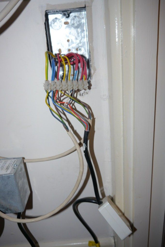
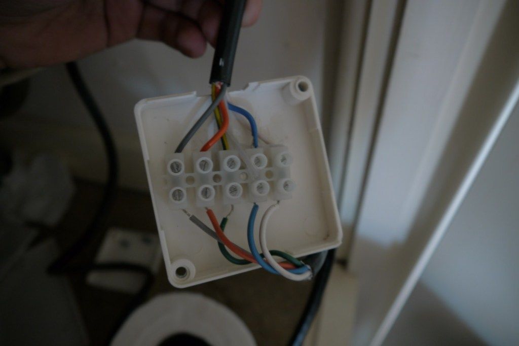
Thanks for the pic; it makes things much clearerThe last question, where do I check this? Is this behind the programmer in the kitchen?
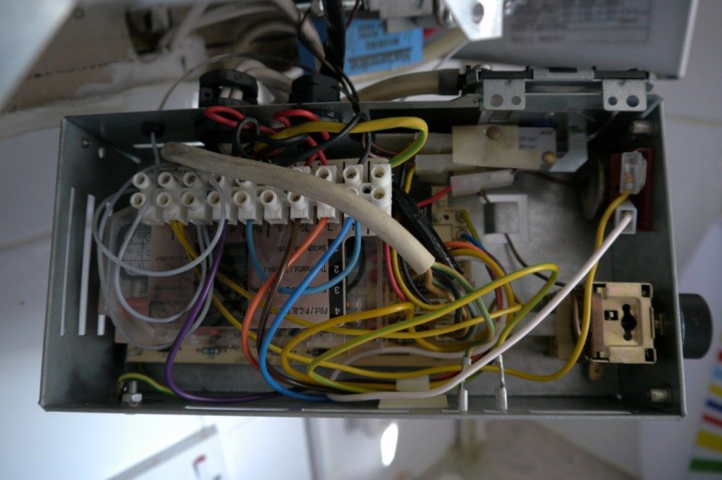
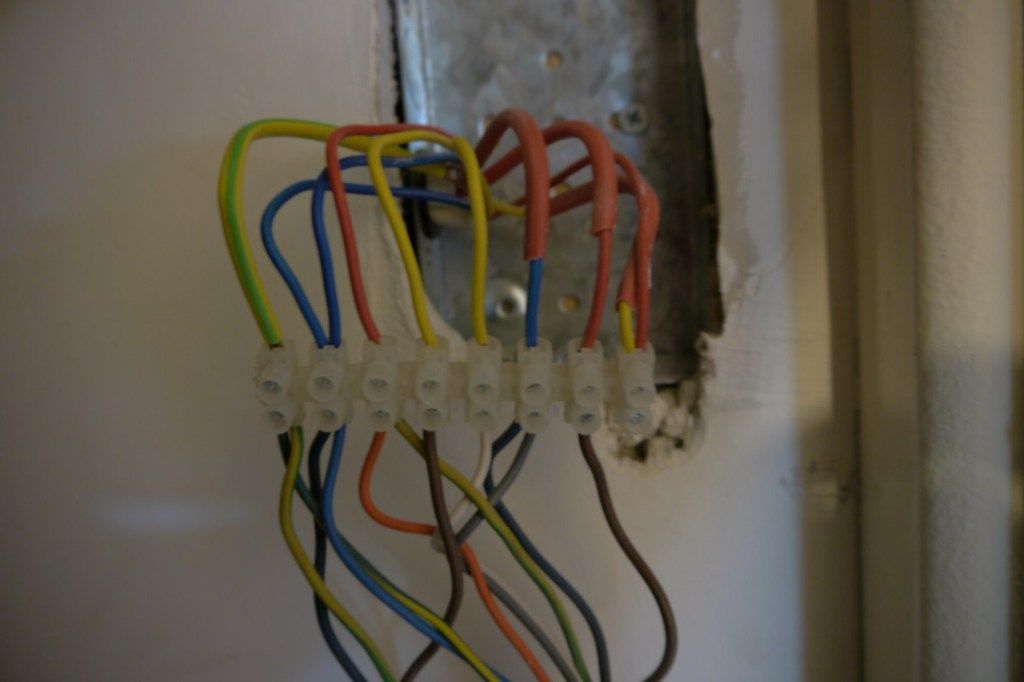
8. Red + Yellow (red sleeve) - don't know what these do
Of course, why didn't I think of that!programmer ch on to roomstat common8. Red + Yellow (red sleeve) - don't know what these do
If you need to find a tradesperson to get your job done, please try our local search below, or if you are doing it yourself you can find suppliers local to you.
Select the supplier or trade you require, enter your location to begin your search.
Are you a trade or supplier? You can create your listing free at DIYnot Local
