
At least we know now, Thanks.

You are using an out of date browser. It may not display this or other websites correctly.
You should upgrade or use an alternative browser.
You should upgrade or use an alternative browser.
12v DC LED Bulb Polarity
- Thread starter SMG
- Start date
Sponsored Links
Not with a bridge (i.e. full-wave) rectifier. In any event, one would not just be connecting a 'passive load' to the output of the bridge - the current throughg the LED will be controlled by circuitry (at its crudest, just a resistor) following the bridge.Yes but with DC you will get twice the watts through one pair of diodes and if half wave or using the LED its self then half the power to LED.I have no idea how these things are normally arranged but, just just thinking aloud, a bridge rectifier (plus appropriate current-controlling components) would enable an LED lamp to work off AC or either polarity of DC.
Kind Regards, John
No, he's right, with a bridge rectifier you will get the entirety of the current passing through just two diodes.
This is, of course, far less of a problem than it used to be, as high (relatively speaking) current diodes and rectifiers are exceedingly cheap today.
Who are you saying is right (and wrong!) about what? The whole point of using a bridge rectifier (a technique which has been used for decades to enable DC-powered equipment to be supply-polarity-independent) is that the current will only flow through two (of the four) diodes, which two depending on the polarity of the DC supply. That's not a problem, it's the whole basis of the concept!No, he's right, with a bridge rectifier you will get the entirety of the current passing through just two diodes.Not with a bridge (i.e. full-wave) rectifier. In any event, one would not just be connecting a 'passive load' to the output of the bridge - the current throughg the LED will be controlled by circuitry (at its crudest, just a resistor) following the bridge.Yes but with DC you will get twice the watts through one pair of diodes and if half wave or using the LED its self then half the power to LED.I have no idea how these things are normally arranged but, just just thinking aloud, a bridge rectifier (plus appropriate current-controlling components) would enable an LED lamp to work off AC or either polarity of DC.
I didn't really understand what point eric was trying to make. His reference to 'twice the watts through the diodes' and 'half the power with half-wave (I presume he meant rectification) seems to imply that he was thinking that the bridge rectifier was being fed with AC - which is obviously not what I was talking about.
Kind Regards, John
A bridge rectifier is rated for rectifying AC, not sorting out the polarity of a DC input. If you feed it DC, only two diodes will conduct, and the rating must be reduced.
Sponsored Links
Are you just quibbling about the fact that I refered to it as a 'bridge rectifier', rather than 'a ring of four diodes'? As I said, it's been a recognised way of 'sorting out the polarity of DC' for decades - and I've made it clear all along that I was talking about DC. Indeed, this whole thread has been about the polarity of DC LED lamps.A bridge rectifier is rated for rectifying AC, not sorting out the polarity of a DC input. If you feed it DC, only two diodes will conduct, and the rating must be reduced.
As for 'the rating must be reduced', even that's not true in terms of maximum current rating since, even with AC only one pair of diodes is conducting at any given point in time (after all, AC is effectively DC which keeps changing polarity!).
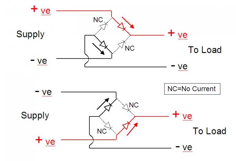
In case anyone is not clear of what I'm talking about, this is the standard arrangement for using 'a ring of 4 diodes' (aka 'bridge recifier') to provide a DC output of fixed polarity, regardless of the polarity of the DC supply:
Kind Regards, John
Are you just quibbling about the fact that I refered to it as a 'bridge rectifier', rather than 'a ring of four diodes'?
No.
As for 'the rating must be reduced', even that's not true in terms of maximum current rating since, even with AC only one pair of diodes is conducting at any given point in time (after all, AC is effectively DC which keeps changing polarity!).
Continuous current =/= peak current. Sine waves are not effectively DC changing polarity.
C'mon, isn't this heading towards 'arguing for arguing's sake'? I suppose it is a hot Saturday nightContinuous current =/= peak current. Sine waves are not effectively DC changing polarity.As for 'the rating must be reduced', even that's not true in terms of maximum current rating since, even with AC only one pair of diodes is conducting at any given point in time (after all, AC is effectively DC which keeps changing polarity!).
")
Anyway, have you not shot your argument in the foot? As you say, peak current is not the same as continuous current (nor is it the same as the RMS current of sinusoidal AC), but diodes are rated for (amongst other things) their maximum peak current. For a given power supplied to the load, the peak current through the diodes if the supply is AC will be greater than the 'peak' (constant) current through them if the supply is DC. Hence, for a given power supplied to the load, the peak current rating of the diodes will have to be greater, not lower, if the supply is AC than if it is DC, won't it? The 'average' current through each diode would, of course, be less with AC, since it would be alternately shared between two diodes, and not just one (as with DC), but that's no consolation if the maximum peak current rating of the diodes is exceeded.
Kind Regards, John
Peak currents are time limited, the thermal mass of the diode determines how much peak current can flow and for how long before the diode overheats to the point of destruction.
A bridge rectifier rectifying AC will be dissipating the heat from 4 diodes. When the same bridge rectifier is used with a DC supply only two diodes are dissipating the same amount of heat that 4 would be when the supply is AC
Running on DC the maximum safe continuous current may be less than the maximum safe continuous current for AC
The derating for use on DC depends on the construction and method of heat disipation inside the bridge rectifier
Yes, I agree with that, but I'm not really sure what/why we are arguing about. As I said, the use of a diode bridge to achieve supply polarity independence for DC equipment is very well established, and I have used in countless times (for currents varying from trivial to very large) over the years/decades. All that matters is to make sure that the diodes can cope (at operating temperature) with the DC currents involved - not a problem with present-day components. Nor did I necessarily mean custom-made 'bridge rectifiers'; on the contrary, I've usually used discrete diodes for this purpose.Peak currents are time limited, the thermal mass of the diode determines how much peak current can flow and for how long before the diode overheats to the point of destruction. A bridge rectifier rectifying AC will be dissipating the heat from 4 diodes. When the same bridge rectifier is used with a DC supply only two diodes are dissipating the same amount of heat that 4 would be when the supply is AC. Running on DC the maximum safe continuous current may be less than the maximum safe continuous current for AC. The derating for use on DC depends on the construction and method of heat disipation inside the bridge rectifier
I've discussed one of the technicalities of the above in an 'Aside for techies' spin-off thread. ( click here ).
Kind Regards, John
DIYnot Local
Staff member
If you need to find a tradesperson to get your job done, please try our local search below, or if you are doing it yourself you can find suppliers local to you.
Select the supplier or trade you require, enter your location to begin your search.
Please select a service and enter a location to continue...
Are you a trade or supplier? You can create your listing free at DIYnot Local
Sponsored Links