250V / 500V IR differences

Joined
28 Jan 2011
Messages
56,252
Reaction score
4,188
Location
Buckinghamshire
Country
United Kingdom
We recently discussed (supplemented by some experiments I did with some bits of wet card!) how attempts to measure IR with very low voltages (e.g. with a multimeter) can give seriously high results (hence potentially dangerously misleading) as compared with results obtained with a proper IR meter using a high (usually 500V) test voltage. However, my experiments at that time seemed to indicate that any DC test voltage above about 30-50V gave much the same results.

Today I replaced a damaged metalclad socket in my daughter's garden shed, and dutifully undertook a few tests of the circuit. The shed is fed by about 20m of buried 4mm² SWA (inherited, so details of installation unknown), and has a mini CU, a couple of double sockets (never appreciably loaded) and a lighting circuit.

The Zs was fine from the shed. IRs (with nothing connected) were all >200 MΩ at 250V, but only about 3 MΩ at 500V and 1000V. I've never seen a marked difference between 250V and 500V (or 1000V) IR results before - what are other people's experiences?

I'm not too worried about the 3 MΩ figure (maybe due to moisture in some of the shed's accessories?) - when I have a bit more time, I'll investigate the circuit a bit more fully, to ascertain exactly where the lowish IR (at 500V) is coming from. However, I am intrigued and surprised by the 250V/500V difference.

Kind Regards, John
 
Sponsored Links
Did it immediately report 3M, or did it take a while to "warm up" to that value?
Did it go back to the higher resistance afterwards?
 
Did it immediately report 3M, or did it take a while to "warm up" to that value? Did it go back to the higher resistance afterwards?
With an MFT, you can't watch a varying result - you just get a single result (after a second or two) each time you press the test button. The very first measurement at 500V was around 3 MΩ. I repeated it several times over a period of time. Results varied, but mainly in the range 2.8 - 4 MΩ (with no pattern to changes - e.g. progressively up or down), and I never saw a result over 5MΩ at 500V or 1000V. Conversely, despite several repeats, I never got a measurable IR (i.e. always ">200 MΩ") at 250V, even after I had undertaken the 500/1000V measurements (which produced the very much lower IR results).

Kind Regards, John
 
It depends on the meter. On my metrel MFT if you press and hold the test button it gives you a variable result.
 
Sponsored Links
It depends on the meter. On my metrel MFT if you press and hold the test button it gives you a variable result.
AFAIAA, I can't do that with my Fluke 1652 - but maybe that's because I've never tried. I'll have a go (and will read the manual)!

Kind REgards, John
 
Fluke is the same, the button is held and you can see the value changing, such as on long circuits where the value will increase over a few seconds due to the capacitance of the cable.
 
Fluke instructions: ... Same process applies for continuity - holding the button is essential.
Yes, I obviously realise that (otherwise I would never have been able to use the machine!). However, my point was that, AFAIAA, (nearly always following a very rapid 'settling' process, during which time figures usually can't be read) once the machine has 'beeped' the display reading is locked, even if one continues to hold the button pressed beyond that point in time - so (again, AFAIAA) any subsequent changes in IR are not seen unless one presses the button and starts the process again. However, I've yet to 'do the experiment' - so watch this space!

Kind Regards, John
 
... so (again, AFAIAA) any subsequent changes in IR are not seen unless one presses the button and starts the process again. However, I've yet to 'do the experiment' - so watch this space!
OK, the experiment is done, and I was wrong :oops: 
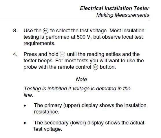
If one keeps one's finger on the button after the machine beeps, the display/measurement is not 'locked' and it does, indeed, show subsequent changes in the resistance so long as the button remains pressed. I can't believe it has taken me so many years to discover this!

However, I'm not sure that this necessarily helps me to understand what I experienced. In practice, I think I do usually keep the button pressed long after the bleep, and, whatever, it's certainly the case that I will have used the meter identically with both 250V and 500/1000V tests - yet I got (consistent) results at 250V which were dramatically different from the (consistent) results I got at 500/1000V. Am I overlooking something?

Kind Regards, John
 
Going back to the original pint we usually test at 5kV on a Megger. The version I use has different voltage settings (500V, 1kV, 2,5kV and 5kV) it is common to get a different resistance reading depending on voltage.

We've never figured why!
 
Going back to the original pint we usually test at 5kV on a Megger. The version I use has different voltage settings (500V, 1kV, 2,5kV and 5kV) it is common to get a different resistance reading depending on voltage. We've never figured why!
That's interesting - but I wonder whether you commonly see differences as dramatic as I reported?

I can see that, when testing long cables (as I imagine you are often doing), there is more scope for mis-measurement at higher test voltages, since there is presumably quite a bit of capacitance involved, and one would expect 'settling time' to be greater with higher voltages (and that may be missed if one is not patient enough). However, the circuit I was testing was no more than 25m in total length, at most, so I would have thought that capacitance-related issues would be pretty minimal.

Kind Regards, John
 
My understanding of the physics is that you'll either get breakdown, in which case the resistance will not return to normal afterwards, or you'll get a heating effect, in which case it would probably have a noticeable warm up / cool down time. A reversible but non-thermal effect, as you're seeing, is harder to explain.
 
My understanding of the physics is that you'll either get breakdown, in which case the resistance will not return to normal afterwards, or you'll get a heating effect, in which case it would probably have a noticeable warm up / cool down time. A reversible but non-thermal effect, as you're seeing, is harder to explain.
Exactly. I didn't actually say this, but once I detected the anomoly, I repeatedly jumped backwards and forwards between 250V and 500V, with consistent results. Immediately after (seconds) I'd got a ~3 MΩ reading at 500V, I would get a >200 MΩ reading at 250V, and vice versa. AFAICC, that essentially rules out either breakdown or thermal effects - and, as for the latter, I do not think that a few tens of mW for a few seconds would have any significant thermal effect, anyway.

It will be interesting to see if I still get similar results when I repeat the measurements, probably in a few days' time.

Kind Regards, John
 
Your results are interesting and for such a huge difference between the two one can rule out capacitance one would think. However having said that my battery meter I always do a short reading to conserve the batteries but with the PAT tester mine a very old Robin has a meter not a digital display and I have noted a few times a low reading which seems to stay that way for a few seconds and then the needle starts to drop quite quickly.

What I wonder is if that point where reading starts to drop will be reached quicker with 250 volt reading as the inverter in the meter must have a limited output. Until you re-test holding the button will will not know of course.
 
Leaky insulation can be caused by many different things. Dampness, chemical breaking down of the insulation material. carbon deposits from scorched cable.....and several others.

Some of these will have a resistance that is voltage dependent. For example dampness leads to corrosion which can produce metal to metal oxide junctions which have a semi-conductor effect which has a break down voltage. The junction will appear as a perfect insulator when tested below the breakdown voltage and a low impedance ( poor insulation ) when the test voltage is higher than the break down voltage.
 

DIYnot Local

Staff member

If you need to find a tradesperson to get your job done, please try our local search below, or if you are doing it yourself you can find suppliers local to you.

Select the supplier or trade you require, enter your location to begin your search.


Are you a trade or supplier? You can create your listing free at DIYnot Local

 
Sponsored Links
Back
Top