2nd 100v Amp blown :( Help needed to troubleshoot.

Joined
24 Feb 2007
Messages
558
Reaction score
3
Country
United Kingdom
Hi guys, I've moved into a house that has a 100v Amp powering 8 ceiling speakers over 4 zones. Each zone has a twist volume control on the wall.

Everything was working fine then the sound became quiet and washy, the amp blew and stopped working.

I purchased a 2nd hand amp from eBay and again it worked fine for a few months then the same happened.

I'm lost without music and want to replace the amp but am obviously fearful that the same will happen again.

If anyone has an suggestions or anything that should be doing to try and fix it would be really helpful.

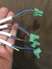
I've so far been round the wall volume controls and checked for any shorts or loose wires and everything is in check.

Many thanks,

Devs.

P.S. I'm not a spark so be gentle.
 
Sponsored Links
what's the rating of the speakers? Do you think they were wired by an audio specialist, or a DIYer?

What does "the amp blew" mean? Internal fuses blew?
 
Do you have the right impedence on the speakers. If it's supposed to be 8ohms and you've got 4ohm speakers, then you could be drawing too much power though the amp. What's the Amp, and the speakers. I assume that plus and minus has been wired correctly, but that shouldn't cause an issue with the Amp, just the quality of the sound.
 
Thanks very much for the replies gents.

The speakers were wired by the same spark that wired the whole house and everything seems to be of a high standard.

The current Amp (last to blow) is an APart MA200 (http://www.apart-audio.com/Category...cat5=2050_MIXING_AMPLIFIERS&productcode=MA200)

The Speakers are APart CM5E (http://www.apart-audio.com/Category...0_BUILTIN&cat5=1010_CEILING&productcode=CM5EH)

The first AMP that failed, (can not remember the make/model but was informed that it wasn't cheap). This failed to power up and had no replaceable internal fuse. Took to a repair shop who stated it was beyond repair.

The APart MA200 failed to power up and blow the internal fuse. Every time I replaced this and connected to power only the fuse continued to blow :(

Not sure whats going on or if its just unlucky.

This is the amp that I intend to replace the others with.. http://www.ebay.co.uk/itm/Adastra-R...oth/232439015614?_trksid=p2485497.m4902.l9144

Thanks again,

Devs.
 
Links in this post may contain affiliate links for which DIYnot may be compensated.
Sponsored Links
Sorry, but you're way beyond my experience with that sort of setup. The speaker immpedences match, so there's nothing obvious, so I suspect you may have been unlucky. The repair shop said it was beyond repair, but did they say why, as that may have indicated the problem. Obviosuly, make sure there are no short circuits on the speakers etc, and check that the speaker cables aren't running near electrica cables that might be causing feedback.
 

I have had peripheral involvement with theatre systems, where the JBL speakers are the size of refrigerators.

I vaguely recall seeing in the tech specs that they have circuit protection so that if the wires are cut or shorted, the components are not damaged. IIRC it is more common for the speakers to be damaged than the amps.

But this is not something I looked into, and I have no understanding of what has gone wrong in your case.

With luck some of the specialists will look in over the weekend.

If not, have a look at http://www.blue-room.org.uk/

For some reason it works better for me on Firefox than on Internet Explorer.
 
Last edited:
If the sound went quiet and non-dynamic then you've got a short on the system somewhere. Quite irritating to diagnose since each speaker is fed via a transformer (which will look like a short circuit to most multimeters).

EDIT AGAIN- I'll leave the rest cos it may still apply but....

The local volume controls- do you know if they are wired on the 100v side or the 8 ohm side? And how are they wired- each control should have 3 wires into it- ground, signal in and signal out. Ground should be at one end of the pot, signal in at the other end, signal out on the variable pin (ground commoned). If each zone has 2 speakers on it then each pot has to handle up to 16 watts- which makes them quite chunky and expensive. If a spark wired it he may not actually have known what he was doing. 100v line in a domestic installation is unusual, unless the cable runs are massive (20m plus) then 8 ohm would be fine.

EDIT AGAIN. You say the thing is set up in zones. Presumably you're feeding the same signal to all 4 zones? In which case the local twist volume controls will be handling about 16w

Your MA200 probably still works- the output fuse has hopefully protected the output stages of the amplifier. EDIT just reread initial post- if the fuse is popping with no speakers connected then that isn't a good sign. If you feel brave, have the lid off, disconnect the output side of the amp from the 100v line transformer and try powering up. If the fuse goes again then amp is probably FUBAR.

First thing is to meter the cabling (disconnect all transformers). If you're lucky there'll be a big fat short in the cabling somewhere- find it and you're laughing.

If the cabling checks out then connect 1 speaker back up to the cabling, put the amp on the other end and see if it works and sounds loud and full. Reconnect speakers one by one until the fuse blows/everything goes quiet.
Remove the last speaker you connected, try it now. Add remaining speakers (NOT the one that blew the fuse).
 
Last edited:
Guys thanks for all your help! This forum never ceases to amaze me!

oldbutnotdead your post was gold and I apoligise for the brief response (theres not much I can say at this stage) but you have given me what is required to resolve my issue.

Many thanks all, Devs.
 
Hi oldbutnotdead, I've come back with a few comments if you have a few mins to take a look when you can. It'd be greatly appreciated :)

The local volume controls- do you know if they are wired on the 100v side or the 8 ohm side? I’m not sure is there a way that I can visually check? And how are they wired- each control should have 3 wires into it- ground, signal in and signal out. Ground should be at one end of the pot, signal in at the other end, signal out on the variable pin (ground commoned). I’ve attached a photo below of one of the pots. (downstairs hall)

IMG_3558.JPG


The zones are set as follows..

1 - Kitchen / Dining room - 3 x speakers / one twist vol. control

2 - Downstairs Hall - 1 x speaker / one twist vol. control

3 - Living Room - 1 x speaker / one twist vol. control

4 - Upstairs Landing - 1 x speaker / one twist vol. control

5 - Master Bed / ensuite 2 x speakers / one twist vol. control

To add to the above there is a wire outside ready to accept a speaker thats yet to be fitted. Im not sure where this is volume controlled? maybe via the Kitchen / Dining as thats the closest.


EDIT AGAIN. You say the thing is set up in zones. Presumably you're feeding the same signal to all 4 zones? In which case the local twist volume controls will be handling about 16w - I’ve been feeding all speakers via an apple Air-Port / Spotify. As I wanted something that I could control via my phone.


First thing is to meter the cabling (disconnect all transformers). If you're lucky there'll be a big fat short in the cabling somewhere- find it and you're laughing. Would you mind please explaining this a little more for me, as I’d like to give it a go. What transformers would I need to disconnect and how would I carry out the metering?

Thanks again,

Devs.
 
This gets interesting. I take back the comment about the spark not knowing what he was doing (though that's still more than I'd pay for a distributed audio system)- pricey way of kitting a house out but hey ho.....

Looking at the wiring, those controls are on the 100v line side (the IN terminals connected to the amp outputs). Those controls (attenuators) usually contain the audio transformer as well so the output will be connected to the loudspeakers direct. You may have to verify this.

The terminals marked 24v are for use in a PA situation- where you have local control of normal program level but if the fire alarm is activated 24v will override local volume settings (for run away messages).

Cabling is well oversize for 100v line (the system at Olivers Mount, covering 2 miles, runs on 1mm twin). Using the 3rd core to earth the backboxes isn't a good idea

My suspicion is you're getting a short on the 100v distribution system. This could easily be caused by a stray strand at one of your control points.

JOB 1. Disconnect amplifier, measure the impedance of the system (using a multimeter set to OHMS across the 2 cores feeding the speakers). This may give you a very low reading (cos transformers) but it might be useful. While at the amplifier end, see what the green and yellow conductor in the speaker flex is connected to.
JOB 2- inspect all the volume controls looking especially for stray copper strands causing short circuits.EITHER Get some bootlace ferrules and reterminate all the flex connections (the flex used is too big for the terminals, high risk of shorts between adjacent conductors) OR get some terminal block and 1mm two core flex, use terminal block to connect your oversize flexes to a short length of 1mm, connect the 1mm flex to the control . Leave the BLUE terminals on the INPUT side hanging loose for now (crimp the ferrule on but don't connect it to the control. Crimp and reconnect the other cables. TIP- disconnect, crimp and reconnect 1 pair at a time at each control so you don't get confused and end up having a speaker getting 100v line direct.
JOB 3- when you've done that, remeasure the system impedance from the amplifier end. It should be open circuit (cos you left all the blue inputs hanging)
JOB 4- measure the impedance at the INPUT of one of those controls. See if it varies with the setting on the volume control. Repeat with all the other controls. Are there any significant differences?
JOB 5- Reconnect the amplifier. Connect one BLUE INPUT terminal, run some music, does it sound OK? Repeat with your other zones til the whole system is reconnected.

The wire ready for an outside speaker is most likely not on a volume control. If you wanted a speaker out there presumably you'd want to control the volume out there too so you'd need another volume control.
 
Many thanks again for the super helpful reply. I’m a novice, but if I can do this I’m more than willing to give it a go as its been driving me mad.


The house is new to me and all the wiring was in place what I bought it, the original owners didn’t scrimp on anything. I suppose the biggest issue that I have at the moment is the lack of an amp. I had a look back on the one that I posted previously above from eBay and it doesn’t appear to have the appropriate inputs for what I require. Is there a particular amp that you would recommend that doesn’t cost the earth and is internally fused?


I don’t own a multimeter but will buy the following now. https://www.amazon.co.uk/ULTRICS®-D...TF8&qid=1505131801&sr=8-2&keywords=multimeter I trust its fit for purpose? I’m not 100% sure how to perform measure the impedance? Is this via connecting the probes to each of the wired pairs at the amp end and looking for differences in the OHMS readings between them?


I’ll pick off one job at a time and hopefully resolve the issue :)
 
That meter will do- there should be an instruction manual with it that will tell you how to perform basic tests (which is what you are doing).

Quick rewind- the MA200 that keeps blowing fuses- is that with speakers connected or without?

Replacement amp (if you need one)- do you need 4 separate output zones? And what inputs do you need that the Adastra doesn't have? That range are not hifi quality but solid and reliable- I've installed several & they're all still running. And you don't need super levels of output protection in your setup (you aren't touring it or constantly moving stuff around)- what you need to do is find the fault in the cabling (and I expect it'll be in one of those terminal blocks due to oversize cable).
 
Hello mate, thats great and I've just ordered the meter.

The MA200 is blowing without the speakers, (but I feel it was shorted via a stray screw that was left rattling around when the amp was opened) :(

Attached is how my current to amp wires are configured so I assumed that I needed the 4 zones? I've also attached an image of the back of the amp that I intended to buy and it doesn't seem to be able to accept?


Thanks again,

Devs.
 

Attachments

  • 953114_IN1.jpg
    953114_IN1.jpg
    113.6 KB · Views: 347
  • IMG_3559.JPG
    IMG_3559.JPG
    165.8 KB · Views: 294
Well one bit of good news- matey who cabled the thing hasn't connected the green/yellow cores to anything at the amplifier end. Do yourself a favour- when you go round all the volume controls rewiring them snip the green/yellows (or disconnect them from the backbox anyway)- that way neither you or anyone else will be thinking that the backboxes are earthed.

Do you have any need to switch the individual zones off at the amplifier? I suspect not- if you want to turn one room off you'd be doing it at the local volume control wouldn't you? So on that new amp you would parallel all 4 pairs onto COM and 100v.

Just been having a look at the manual for that MA200- it suggests the minimum system impedance should be 50 ohms. Your new multimeter won't measure impedance properly (IIRC the varying voltage on the signal lines induces back EMF in the transformer primary & that's where your impedance comes from. Your meter will be using DC and measuring resistance). If you want to play it a bit safe, stick a 100w lightbulb (can you get them still?) in series with the speaker wires at the amplifier (so on the back of the amplifier, all 4 blue wires would go to the COMMON terminal. 1 wire from the 100v terminal goes into one side of the lampholder, the 4 brown wires go into the other side of the lampholder. The lightbulb acts as a big resistor- again if you test it with your new meter it'll show about 3 ohms. But as the filament carries current and gets warm the resistance increases...... this will reduce your overall output level but will keep the system impedance up :)
 
Good suggestion mate, I’ll snipe those earths whilst I go around.


Correct I’d have no need to switch the individual zones off at the amplifier. I’ll order that amp now so I’ll have it in a few days for further testing. When you say “ you would parallel all 4 pairs onto COM and 100v.” should I be connecting the wires via a junction box first or directly into the amp? Also would it be brown to the 100v connection?


I must say I do not 100% follow you with the below… I’m just off to see if I have an old 100w lightbulb and a fitting. The MA200 amp that I have is fobar’d and fuses everytime. I’m about to replace this now with the Adastra RM120B 5 channel 100V.


“Just been having a look at the manual for that MA200- it suggests the minimum system impedance should be 50 ohms. Your new multimeter won't measure impedance properly (IIRC the varying voltage on the signal lines induces back EMF in the transformer primary & that's where your impedance comes from. Your meter will be using DC and measuring resistance). If you want to play it a bit safe, stick a 100w lightbulb (can you get them still?) in series with the speaker wires at the amplifier (so on the back of the amplifier, all 4 blue wires would go to the COMMON terminal. 1 wire from the 100v terminal goes into one side of the lampholder, the 4 brown wires go into the other side of the lampholder. The lightbulb acts as a big resistor- again if you test it with your new meter it'll show about 3 ohms. But as the filament carries current and gets warm the resistance increases...... this will reduce your overall output level but will keep the system impedance up.”

Also mate, I was wondering should I be checking the connections at the speaker ends? I personally hope not as 3 of them are only accessible via scaffolding.


Thanks as always,


Devs :)
 
Last edited:

DIYnot Local

Staff member

If you need to find a tradesperson to get your job done, please try our local search below, or if you are doing it yourself you can find suppliers local to you.

Select the supplier or trade you require, enter your location to begin your search.


Are you a trade or supplier? You can create your listing free at DIYnot Local

 
Sponsored Links
Back
Top