BS fuses time current characteristics question

Joined
6 Nov 2004
Messages
108
Reaction score
2
Location
Nottingham
Country
United Kingdom
Hi all

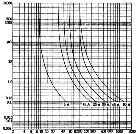
If you look at the time current characteristic charts in BS7671 regs I noticed that for a rated fuse of say 5amps BS3036, the minimum amount of current required to operate that fuse is just less than 9amps!

Am I missing something here? According to that chart, if I have a 4amp rated load protected by a 5amp fuse, the load could draw upto 8.5 amps in an overload condition and the fuse would happily carry the current all day.

Why does the curve not intersect the 5amp vertical line at some point?

Cheers
 
Sponsored Links
I vaguely know the answer to this, I'm sure somebody will be able to interject with a much more detailed answer but it's to do with fault current.

You wouldn't want the fuse to operate bang on 5a as it would blow all the time. If it's a 5a chances are the cable is 1.5mm which will happily take up to around 16a so for it to blow at 9a is perfectly ok.

If there is a fault however, it's gonna send way more than 9a back to the fuse which will cause it to blow immediately, which is what you want.

But imagine if everytime you turned all the lights on at once it blew the fuse because it needed 5.1a (as an example)
 
You wouldn't want the fuse to operate bang on 5a as it would blow all the time.

Of course this would be unacceptable but I was just wondering why the curve isn't moved across to the left a bit on the current axis. For example the 5 amp rated fuse would blow in a reasonable time when the load it was protecting started to draw say 6 amps.
 
Sponsored Links
Because it would get very hot in normal use!

Yes I guess it would but we have some very good heat resisting materials around these days so I can't see that this is the only reason.

I was wondering if it may have something to do with fuse tolerances and ambient temperatures?
 
The current curves are very varied with different protective devices and much depends on what you are trying to protect. Oddly the humble fuse does a better job than the MCB when protecting semi-conductor devices.

It is interesting when one overlays the different curves as to at what current each device will open first.

Although looking at the curve
3.13b.gif
it would seem the 6A fuse will not blow at 7A that is because the curve stops at 10,000 seconds or 2.7 hours if we were for example to fit a 10A BS 1362 fuse in a 3kW kettle it would likely last for years. But in a 3kW immersion heater it would likely blow as it can take hours to heat from cold. One reason why we have dedicated supply to immersion heater.

I am sure the 5A curve does intersect the 5A line at some point but that would be days not hours and much would depend on the cooling. Fuses do of course generate heat and it is the ability to remove this heat which is the major factor in long term use. We use the humble BS 1362 fuse in many different fuse holders made from many different materials mainly plastics but clearly with vastly different cooling characteristics and we should be able to put a 5A fuse in them all without it failing on 5A so clearly there must be some leeway in the exact temperature that it will blow with 5A.

With a MCB the situation is different. Here like the fuse there is a thermal component but the curve would result in the blowing time with massive overload being rather slow so also a magnetic device is incorporated designed purely for the massive overload situation.

By using two devices in one the curve is compacted but still the standard B type (6A) will still allow around 8.5A for 2.7 hours. This is clearly not what is wanted to protect motors.

So both with the fuse and with the MCB there are special ones designed for motor protection. Years ago motor protection was all magnetic and to stop them tripping on start we used an oil damper to slow the mechanism down enough for the motor to start without it tripping. We then had much more control and selecting the viscosity of the oil we could vary the time for which the overload could exist for.

But as with rewireable fuses people would cheat. EP90 in dash pot would really delay tripping. With an electrician who should understand what he is doing this is OK but with the general public to have a trip where they can vary the characteristics could be dangerous which is why now we have to use cartridge fuses where untrained people can change them.
 
Yes I guess it would but we have some very good heat resisting materials around these days so I can't see that this is the only reason.

We had some very good heat resisting materials in the days rewireables were used industrially and commerially.

It is this material that is the reason why most of these boards now have to be consigned to to scrap and removed suited and masked up and double bagged in haazardous waste sacks at not in-considerable cost!
 
:LOL:

There's a lot to be said for the old boards that had nothing but metal and ceramic in them.
 
Am I missing something here? According to that chart, if I have a 4amp rated load protected by a 5amp fuse, the load could draw upto 8.5 amps in an overload condition and the fuse would happily carry the current all day.
Because that's how OPDs work
You're forgetting the oft-mentioned fact that the fuse is there to protect the cable.
If your 4A load starts to draw 8.5A, as long as the cable is undamaged when the fuse blows, it doesn't matter.

I was just wondering why the curve isn't moved across to the left a bit on the current axis. For example the 5 amp rated fuse would blow in a reasonable time when the load it was protecting started to draw say 6 amps.
Because then it would be a 3A to 4A fuse.
 
With a MCB the situation is different. Here like the fuse there is a thermal component but the curve would result in the blowing time with massive overload being rather slow

A lot of the early MCBs did use the thermal part to achieve disconnection times and most times it was slower than a re-wireable fuse.

If you do the adiabatic equation for a loadmaster type 4 30A breaker with a zs of say 0.62 ohms, you get a very worring answer, especially if the circuit is in 2.5/1 which was around at the same time as these boards! And to hit the magnetic trip on these devices you need a zs of below about 0.33 ohms.

By using two devices in one the curve is compacted but still the standard B type (6A) will still allow around 8.5A for 2.7 hours. This is clearly not what is wanted to protect motors.

There was a type K mcb which had a less sensitive magnetic trip and a more sensitive thermal one. Designed for motor circuits. Only ever seen them for wylex HB boards though
 
If you look at the time current characteristic charts in BS7671 regs I noticed that for a rated fuse of say 5amps BS3036, the minimum amount of current required to operate that fuse is just less than 9amps! ....but I was just wondering why the curve isn't moved across to the left a bit on the current axis. For example the 5 amp rated fuse would blow in a reasonable time when the load it was protecting started to draw say 6 amps.
You have received several qualitative answers, but as a stab at the thinking behind the quantitative answer ...

...as has been said, OPDs exist to protect cables, and it is implicit from the regs that a cable is deemed able to carry 1.45 times its 'maximum current carrying capacity' (as tabulated in the regs) for at least 1 hour without damage. In the most extreme case, of an OPD just low enough in rating (In) to protect the cable, the requirement is therefore that the OPD should operate in 1 hour or less at 1.45 times the In of the OPD. In the case of a 5A fuse, that means it has to operate in 1 hour at about 8.7A - which is what you have observed. Since the curve is virtually vertical by then, it could not be 'moved to the left' without reducing the current required for operation in 1 hour to a lot less than 'needed'.

Kind Regards, John.

Kind Regards, John
 
... it would seem the 6A fuse will not blow at 7A that is because the curve stops at 10,000 seconds or 2.7 hours .... I am sure the 5A curve does intersect the 5A line at some point but that would be days not hours and much would depend on the cooling.
Whilst that would be true of a 'perfectly thermally-insulted fuse', I very much doubt that with any standard format of fuse the 5A curve would ever get anywhere near intersecting the 5A line, no matter how far one extended the time axis, since that would require an extremely high level of thermal insulation. With standard fuse formats in common installation arrangements, I would imagine that by 10,000 seconds one is probably getting close to a situation of thermal equilibrium, and hence close to the situation in which lower currents will result in equilibrium temperatures which the fuse wire is able to tolerate 'indefinitely'. Once one gets down to such a current, the curve obviously becomes literally vertical.

Kind Regards, John.
 

DIYnot Local

Staff member

If you need to find a tradesperson to get your job done, please try our local search below, or if you are doing it yourself you can find suppliers local to you.

Select the supplier or trade you require, enter your location to begin your search.


Are you a trade or supplier? You can create your listing free at DIYnot Local

 
Sponsored Links
Back
Top