Hi,
I know it's not a question about 'utility power' but thought I'd post anyway...
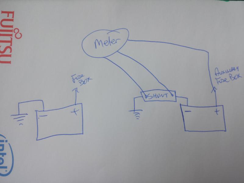
I am having trouble with a DC current shunt connected on an auxiliary battery on my vehicle.
At night when there is no current draw and I calibrate the shunt by zeroing the meter and then putting a 150amp load on and calibrating it all is fine.
BUT come the morning the meter is showing a current of 0.4amps flowing into the battery. There is a quiescent current of something like 0.01amps from electronics etc flowing all the time, but why the difference; could it be down to temperature as the shunt is located on top of the battery in the engine compartment so is subject to temperature changes.
If so, any simple ideas to negate it?
Thanks,
Ian
I know it's not a question about 'utility power' but thought I'd post anyway...
I am having trouble with a DC current shunt connected on an auxiliary battery on my vehicle.
At night when there is no current draw and I calibrate the shunt by zeroing the meter and then putting a 150amp load on and calibrating it all is fine.
BUT come the morning the meter is showing a current of 0.4amps flowing into the battery. There is a quiescent current of something like 0.01amps from electronics etc flowing all the time, but why the difference; could it be down to temperature as the shunt is located on top of the battery in the engine compartment so is subject to temperature changes.
If so, any simple ideas to negate it?
Thanks,
Ian