Elderly relatives freezing hive wiring help

Joined
23 Sep 2023
Messages
20
Reaction score
4
Country
Western Sahara
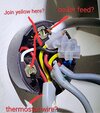
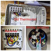
One of my relatives has dementia so I decided getting a hive system would be the best option as I ccan control and manage the heating for them. Unfortunately, I've run into a massive stumbling block and need some urgent wiring help. I am trying to decommission and bypass the old Potterton PRT2 thermostat. The Hive receiver went into where the old British Gas programmer was (the digital one) and all is well with that. I've linked the wireless thermostat/hub/receiver altogether. Now unfortunately my problem is the old thermostat is still wired up to the boiler it seems. So the question is how do I bypass it and what wiring goes where.

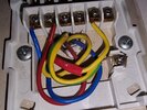
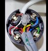
To try and help I've tried to take some pictures of the whole system. My boiler is a combi so this is for central heating only. Am I right thinking the yellow wire is the key one in question, and this needs to go to a permanent live?

Guidance appreciated!
 

Attachments

  • ljohlhn6psba.jpg
    ljohlhn6psba.jpg
    487.5 KB · Views: 74
Sponsored Links
Com is live and H switch live, so maybe join these together and remove the others from junction box or terminal safely.
 
The picture you have posted of the receiver has wiring connections that don't seem to be correct.
If this is the new base for the Hive, how did you decide on these connections?
(Unless you have a dual channel Hive)
 
  • Thanks
Reactions: CBW
Com is live and H switch live, so maybe join these together and remove the others from junction box or terminal safely.

Thanks I'll have a look. It's sort of hard to make heads or tails of the junction box with the way it's all laid out in a clump

The picture you have posted of the receiver has wiring connections that don't seem to be correct.
If this is the new base for the Hive, how did you decide on these connections?
(Unless you have a dual channel Hive)

I didn't actually change the wiring. Just mounted the receiver on directly. With the old BG digital programmer looking pretty much identical as the hive system I presumed it would be like for like?
 
Sponsored Links
Com is live and H switch live, so maybe join these together and remove the others from junction box or terminal safely.
Given the 'urgent' nature of the request and unknown competency of the poster, I personally wouldn't advise removing anything from the junction box.
Bridging H and Com and leaving everything in place should at least work :)


I presumed it would be like for like?
Never presume! What was the model of the old controller, and do you have a single, or dual channel Hive?
 
Given the 'urgent' nature of the request and unknown competency of the poster, I personally wouldn't advise removing anything from the junction box.
Bridging H and Com and leaving everything in place should at least work :)


Never presume! What was the model of the old controller, and do you have a single, or dual channel Hive?

It's a single channel (I went for this option as I've got a combi boiler and no separate hot-water tank) On the receiver, I took the wire on the far right and brought it over one so it 'should' be where the single channel receiver expects to receive HOT ON. Whereas, according to the diagrams the far right position was unused on the single channel device.

If you google 'British Gas DCP' that's what was previously installed. Looks like the old hive system.

So with all being well, I just need to tweak the junction box. Here's another picture. Any thoughts on whether I'm correct in my thinking here?
 

Attachments

  • Screenshot 2023-09-23 104351.jpg
    Screenshot 2023-09-23 104351.jpg
    137.5 KB · Views: 32
So with all being well, I just need to tweak the junction box. Here's another picture. Any thoughts on whether I'm correct in my thinking here?
For the moment, ignore the junction box.
Let's just try and get things working.

On the receiver, I took the wire on the far right and brought it over one so it 'should' be where the single channel receiver expects to receive HOT ON
Yes, that's correct.
Also on the single channel Hive, you will need an extra wire to connect Live and terminal 1 (Com)

And on your PRT2, you have a small brown cable going between terminal 2 and terminal 4.
Connect this between terminal 2 and terminal 3 instead.
This will bridge out the thermostat.
 
For the moment, ignore the junction box.
Let's just try and get things working.


Yes, that's correct.
Also on the single channel Hive, you will need an extra wire to connect Live and terminal 1 (Com)

And on your PRT2, you have a small brown cable going between terminal 2 and terminal 4.
Connect this between terminal 2 and terminal 3 instead.
This will bridge out the thermostat.

Thanks and done. I've bridged the PRT2 as you've suggested (I left the red/yellow wires in situ slotting the brown wire in with them)

On my receiver I've hit a massive snag. No wire suitable for COM. Ugh.
 

Attachments

  • 20230923_132030.jpg
    20230923_132030.jpg
    325.4 KB · Views: 24
Last edited:
Thanks and done. I've bridged the PRT2 as you've suggested (I left the red/yellow wires in situ slotting the brown wire in with them)
Yes, good!

On my receiver I have an earth going to COM
From your picture, the earth cable disappears beneath the Com terminal. It does not appear to be connected to it.
If it were, it must come out, and only be connected to the earth terminal.

like the PRT2 am I to bridge as well with an extra bit of wire. Not sure where/what wire would go in there based on what I have otherwise?
You would connect the bridging wire between L and terminal 1 (com) here:

Screenshot_20230923-132419_Pocket Paint.jpg


If you can't find a small piece of wire anywhere to do this, there appears to be enough length spare on the red wire, to enable a bit to be cut off.
 
Just wanted to say THANKS. I must be stupid as I've watched countless videos and I couldn't make heads or tails of what really to do. Everything works exactly as expected. Saved me massively on heating engineer / electricians who are all booked up until next Xmas. I will at some point have to physically remove the old thermostat as I can't leave it in situ (the wall it was installed on no longer exists) I wonder if it's a case of snipping some wires and rejoining them as per the bypass instructions.
 
Everything works exactly as expected
Brilliant, well done! :)

This is the benefit of adjusting the wiring a step at a time. If we started playing with the junction box as well, and it didn't work, we wouldn't know where to look for the problem.

I wonder if it's a case of snipping some wires and rejoining them as per the bypass instructions.
All we have done to bridge out the thermostat is to connect the yellow and red wires in the PRT2 together. If we follow that cable back to the junction box, we can do the same thing.

If this really is the thermostat cable...

Screenshot_20230924-010926_Chrome.jpg

It appears that the red wire is connected to a white, and the yellow wire is connected to a red wire, in a separate terminal block.

If this is the case; to remove the cable completely, we need to connect the red wire in the terminal block to the white wire...

image14.png


I hope that makes sense.
 
  • Thanks
Reactions: CBW
Brilliant, well done! :)

This is the benefit of adjusting the wiring a step at a time. If we started playing with the junction box as well, and it didn't work, we wouldn't know where to look for the problem.


All we have done to bridge out the thermostat is to connect the yellow and red wires in the PRT2 together. If we follow that cable back to the junction box, we can do the same thing.

If this really is the thermostat cable...

View attachment 314869
It appears that the red wire is connected to a white, and the yellow wire is connected to a red wire, in a separate terminal block.

If this is the case; to remove the cable completely, we need to connect the red wire in the terminal block to the white wire...

View attachment 314868

I hope that makes sense.

Sorry for the slow response on this one, life's been a bit frantic at the moment.

OK, so I took took the red/yellow out of the connector and joined the red on to the white and red like below. However, no boiler this time. Can you Mind having another look? Thanks again!!
 

Attachments

  • Screenshot 2023-10-04 160138.jpg
    Screenshot 2023-10-04 160138.jpg
    122.4 KB · Views: 30
So, is it sorted now?
Nope, I'm afraid not. Difference here is the thermostat has been completed removed (not just bypassed as per last week) With both red wires on the same connector as the white wire the receiver is powered but it's not activating the boiler when I try and call for heat. Any thoughts?
 

DIYnot Local

Staff member

If you need to find a tradesperson to get your job done, please try our local search below, or if you are doing it yourself you can find suppliers local to you.

Select the supplier or trade you require, enter your location to begin your search.


Are you a trade or supplier? You can create your listing free at DIYnot Local

 
Sponsored Links
Back
Top