Electric circuit testing

Joined
24 Oct 2011
Messages
67
Reaction score
2
Location
Hampshire
Country
United Kingdom
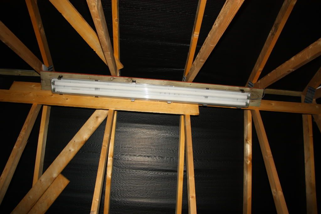
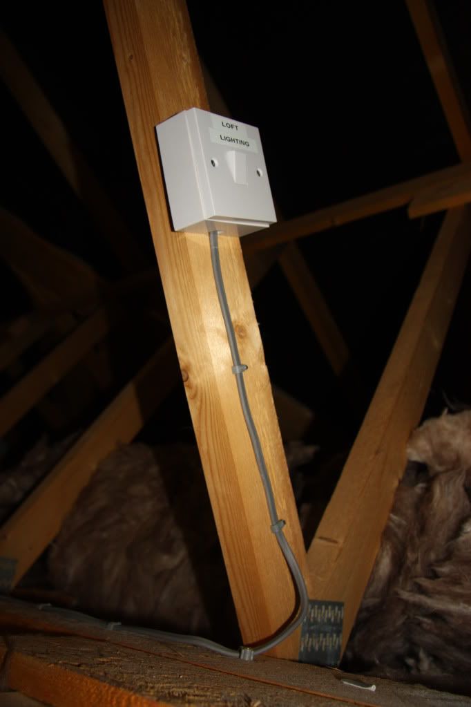
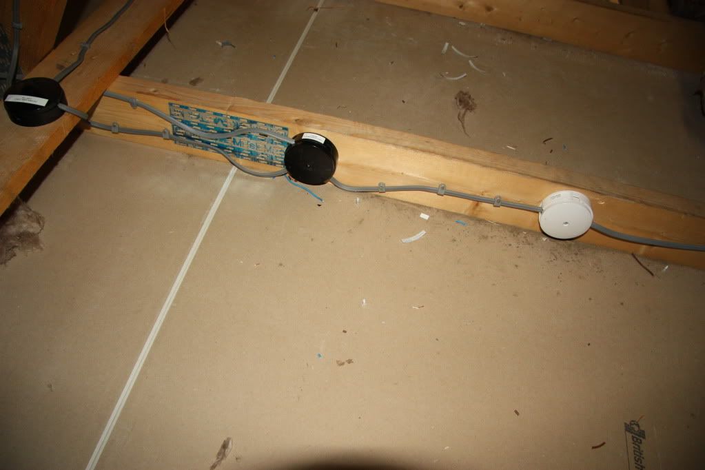
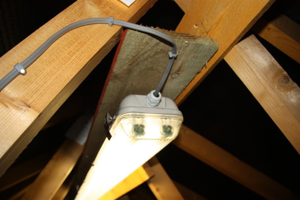
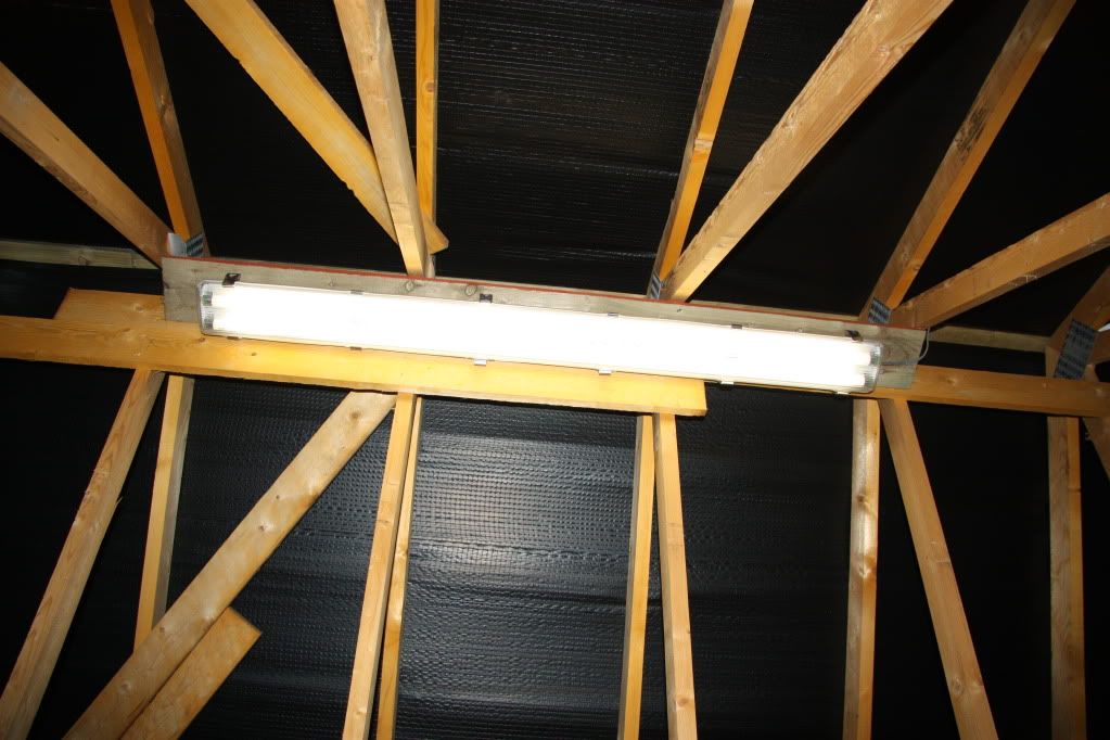
Been a while since I have done DIY electrics in the house. I have wired a new light in the loft of a house I have moved into recently.

So got my earth loop and insulation tester at the ready to finish the connection off. Tested for continuity and all ok. But rusty on the value required for the below tests.

For the earth loop impedance test, is a value 500mOhms and below acceptable?

And for insulation testing, any value above 1Megaohm?

Many Thanks
 
Sponsored Links
You are correct on the value of ≥ 1M Ω for insualtion resistance.

For earth fault loop impedance this needs to be the value equal to or below that which will cause operation of the protective device within the required disconnection time in the event of an earth fault.
For an RCD protected circuit on a TT system this could be several Ohms up to a couple of hundred Ohms.
 
Thanks for confirming the insulation testing.

Its a new consumer unit with mccb for each circuit in the house.

Earthing is PME if that helps.
 
Sponsored Links
For the earth loop impedance test, is a value 500mOhms and below acceptable?

Yes, for any lighting circuit that would be acceptable, to give a precise figure you need to advise the size and type of protective device.

And for insulation testing, any value above 1Megaohm?

Yes, but on a new installation any reading below 4 or 5 MΩ, is an indication that something is wrong, usually a squashed cable.

So I need to find out the Ampere size of mccb that is installed on the lighting circuits?
 
So I need to find out the Ampere size of mccb that is installed on the lighting circuits?

You have got
a new consumer unit with mccb for each circuit in the house.
The information that you need will be on the Installation Certificate that was provided when the new consumer unit was comissioned.

Its also written on the front of the CPD.
 
So I need to find out the Ampere size of mccb that is installed on the lighting circuits?
Indeed. It's very likely to be a 6A Type B MCB, in which case the regs would be satisfied with any loop impedance less than 6.18Ω. However, with your PME supply, something would be very wrong if your earth loop impedance was anything like as high as that.

Kind Regards, John.

Thanks John.

Yes for PME I'd expect an earth loop no greater than 0.35Ω.

I'll post results I get tonight.
 
Thanks John. Yes for PME I'd expect an earth loop no greater than 0.35Ω.
That's as measured at the origin of your supply - the earth loop impedance as measured at the end of a lighting circuit will obvioulsy be greater (because of impedance of the circuit itself) but, as I said, nowhere near 6Ω.

Kind Regards, John.
 
The protective devices if a fuse needs looking up but with a MCB/RCBO then can be calculated. B = 5X, C = 10 and D = 20 so a B6 MCB will trip within the proscribed time at 5 x 6 = 30A. So the loop impedance will need to be less than using ohms law 230/30 = 7.6 ohms.

The are two loop impedances line - earth and line - neutral before the RCD we would take the highest but with RCD protection the line - earth impedance can be much higher. Table 41.5 Note 2 tells us 200 ohms is maximum as above that it is unstable but even a 300ma RCD for fire protection on calculation requires 766 ohms so unlikely with a RCD that you would need a figure below 200 ohms.

The trip times for line - neutral allowed may be longer than the line - earth but because the magnetic part of the trip needs 5, 10, or 20 times the thermal current to trip it's not a sliding scale but a fixed figure. With a fuse the loop impedance being a little high is not cause for real concern but with MCB/RCBO there is a max figure and no leeway.

So 0.5 ohms = 460A so OK for any domestic B type, up to a C45 and a D20 MCB. This for full loop impedance of course. If measured with a low ohm meter then you need to add the incoming loop impedance so 50A, 25A or 13A once the 0.35 ohms of standard TN-C-S supply is added.

Because in days gone by the earth - line impedance was normally higher than the neutral - line impedance we had a tendency only to worry about the ELI and often people would not even test the neutral - line impedance but of course we should test it. But as to disconnection times we see 0.1, 0.4, and 5 second quoted for line - earth but I have not found where it gives line - neutral times so I will admit I am unsure if the line - neutral time was over 5 seconds (point where thermal takes over) if it's really a fail. However it would likely fail on volt drop so really just academic anyway.
 
PS as to size of MCB for lights it is allowed to go up to 16A if the wiring and junction boxes are rated high enough but that is rarely the case. Most ceiling roses are rated at 5 or 6 amp so in practice that's the limit.
 
It's a 6A mccb.

Ok opened the circuit I was tapping into for the new loft lighting..... Did a continuity and got a 'beep' between live and neutral! At first I thought.. 'Damn I've opened a light switch circuit.' however on turning the power back on and doing a polarity test, the brown beeped and the blue neutral didn't. Going between L - N I got 245V which proved it to be a circuit.

Just don't understand how the beep occurred during a continuity test.... Result 11ohms... Unless the signal is going through a load somewhere.....
 
A load on the circuit is the most likely reason. Were there any lightbulbs on the circuit and switches turned on?
 
Possibly. Mostly energy saving in the house. Filament bulb was 65ohms... Energy saving zero due to it being a gas.

Maybe tomorrow I'll get the final connection done then! Was a bit of a mare this evening.... The junction box split when screwed and had to buy another. The existing circuit did not have enough slack to enable the use of one junction box for the tap-in of the new light so had to use 2 and piece a new piece of cable in the middle..... Just to get the lights back on for the misses coming home..
 
Ohwell,

here goes. Some pics of my (un)handy work!


Double tube IP65 light mounted
IMG_7729.jpg


Switch fixed to the trusses
IMG_7730.jpg


Switch cable run to junction box 1
IMG_7732.jpg


Junction box 1
IMG_7734.jpg


Not enough slack in main circuit cable so had to use two junction boxes and piece a section of 1.5mm in place
IMG_7738.jpg


Junction Box 2
IMG_7735.jpg


Junction Box 3
IMG_7736.jpg


Cabling to the light
IMG_7739.jpg


Cabling into the light
IMG_7741.jpg


Lights on!
IMG_7731.jpg


Spent a couple of evenings faffing around doing this. Maybe not the tidiest but I have got lighting in the loft now.
 

DIYnot Local

Staff member

If you need to find a tradesperson to get your job done, please try our local search below, or if you are doing it yourself you can find suppliers local to you.

Select the supplier or trade you require, enter your location to begin your search.


Are you a trade or supplier? You can create your listing free at DIYnot Local

 
Sponsored Links
Back
Top