I have been following the Honeywell Y plan diagram to connect my system and it doesn’t seem to work properly. On the programmer (ST699) I slide the Hot water only button to cont. (continuous) nothing happens, boiler doesn’t fire up. Only when I turn the room thermostat the boiler will fire up and even if I slide the Hot water to off position the boiler is still working, to switch it off I need to turn the room stat to minimum position.
I have not tested Central Heating system as I found problem with the Hot water and didn’t want to cause any damage. So I need to isolate this problem before I move on") I would really appreciate any help, and would love to know how to test with a voltmeter the cylinder stat, room stat so i can illuminate these from being faulty and what readings i should be getting across programmer terminal block and Honeywell 10 way block
I would really appreciate any help, and would love to know how to test with a voltmeter the cylinder stat, room stat so i can illuminate these from being faulty and what readings i should be getting across programmer terminal block and Honeywell 10 way block
Information of Hardware:
Boiler Glow-worm Ultimate 50FF
Cylinder Stat (no manufacturing marking),
Room Stat (no manufacturing marking), very old dial version, and 4 wires connection
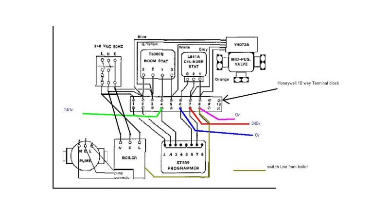
Honeywell mid-position valve – v4073
Honeywell Programmer ST699
Honeywell 10 way terminal block
Wiring configuration:
Boiler
From the boiler L, N, E connected to 10 way Honeywell terminal block,
Boiler Live = Connects to Honeywell terminal block 8,
Boiler Neutral =Connects to Honeywell terminal block 2,
Boiler Earth= Connects to Honeywell terminal block 3.
Note: I have a one link across SL and 9 and second link across K1 and K2
Pump
From the pump the 3 wires L, N, E are connected as follow:
Pump Live = Connects to Honeywell terminal block 8{same as boiler live}
Pump Neutral = Connects to Honeywell terminal block 2 {same as boiler neutral}
Pump Earth = Connects to Honeywell terminal block 3 {same as boiler earth}
Programmer ST699
*Inside the programmer I got links across terminal 1-5-8
Programmer terminal L* is connected to Honeywell terminal block 1
Programmer terminal N is connected to Honeywell terminal block 2
Programmer terminal 3 is connected to Honeywell terminal block 4
Programmer terminal 4 not connected
Programmer terminal 5* Links to 1 and 8 inside the programmer terminal
Programmer terminal 6 is connected to Honeywell terminal block 6
Programmer terminal 7 is connected to Honeywell terminal block 7
Programmer terminal 8* Links to 1 and 5 insider the programmer terminal
Honeywell terminal block 10 Way:
Terminal 1 is connected to Live Load on FCU (Spur)
Terminal 2 is connected to Neutral on FCU (spur) + Room Stat blue wire + Mid-Position valve blue wire.
Terminal 3 is connected to Earth on FCU (spur) + Room Stat G/Yellow wire + Mid –Position valve G/yellow
Terminal 4 is connected to Programmer ST699 terminal 3 and Room stat (1) Red wire
Terminal 5 is connected to room stat (3) Yellow wire and also mid-position valve white wire.
Terminal 6 is connected to Programmer ST699 terminal 6 and Cylinder stat (Common) brown wire
Terminal 7 is connected to Programmer ST699 terminal 7 and Cylinder stat (2) G/Yellow wire and mid-position valve Grey wire
Terminal 8 is connected to Boiler Live(which goes back downstairs to the boiler terminal control box marked L) + Pump Live and Cylinder stat (1) Blue wire and mid-position valve Orange wire.
Terminal 9 is Not used
Terminal 10 is Not used
What I found conflicting and really confusing some Y-plan diagrams I read show that the pump Live goes back to the boiler marking P terminal in its control box( someting about over run was mentioned). And boiler has a permanent live feed to L. The SL is connected to mid-position valve orange wire and to cylinder stat terminal (1). Is this method correct?
off question, just for my reference, How do I find out what type of system is installed i.e. A gravity domestic hot water and pumped central heating system or a Fully pumped open vented system. How does one distinguish this. This is what i have fitted :
I have a tank in my loft and the pipes come down to my airing cupboard in the bath room where the cylinder, pump, mid-position valve, programmer ST699 and Honeywell terminal box is fitted and the boiler is fitted downstairs in the kitchen.
Thanks in advance
I have not tested Central Heating system as I found problem with the Hot water and didn’t want to cause any damage. So I need to isolate this problem before I move on
I would really appreciate any help, and would love to know how to test with a voltmeter the cylinder stat, room stat so i can illuminate these from being faulty and what readings i should be getting across programmer terminal block and Honeywell 10 way blockInformation of Hardware:
Boiler Glow-worm Ultimate 50FF
Cylinder Stat (no manufacturing marking),
Room Stat (no manufacturing marking), very old dial version, and 4 wires connection
Honeywell mid-position valve – v4073
Honeywell Programmer ST699
Honeywell 10 way terminal block
Wiring configuration:
Boiler
From the boiler L, N, E connected to 10 way Honeywell terminal block,
Boiler Live = Connects to Honeywell terminal block 8,
Boiler Neutral =Connects to Honeywell terminal block 2,
Boiler Earth= Connects to Honeywell terminal block 3.
Note: I have a one link across SL and 9 and second link across K1 and K2
Pump
From the pump the 3 wires L, N, E are connected as follow:
Pump Live = Connects to Honeywell terminal block 8{same as boiler live}
Pump Neutral = Connects to Honeywell terminal block 2 {same as boiler neutral}
Pump Earth = Connects to Honeywell terminal block 3 {same as boiler earth}
Programmer ST699
*Inside the programmer I got links across terminal 1-5-8
Programmer terminal L* is connected to Honeywell terminal block 1
Programmer terminal N is connected to Honeywell terminal block 2
Programmer terminal 3 is connected to Honeywell terminal block 4
Programmer terminal 4 not connected
Programmer terminal 5* Links to 1 and 8 inside the programmer terminal
Programmer terminal 6 is connected to Honeywell terminal block 6
Programmer terminal 7 is connected to Honeywell terminal block 7
Programmer terminal 8* Links to 1 and 5 insider the programmer terminal
Honeywell terminal block 10 Way:
Terminal 1 is connected to Live Load on FCU (Spur)
Terminal 2 is connected to Neutral on FCU (spur) + Room Stat blue wire + Mid-Position valve blue wire.
Terminal 3 is connected to Earth on FCU (spur) + Room Stat G/Yellow wire + Mid –Position valve G/yellow
Terminal 4 is connected to Programmer ST699 terminal 3 and Room stat (1) Red wire
Terminal 5 is connected to room stat (3) Yellow wire and also mid-position valve white wire.
Terminal 6 is connected to Programmer ST699 terminal 6 and Cylinder stat (Common) brown wire
Terminal 7 is connected to Programmer ST699 terminal 7 and Cylinder stat (2) G/Yellow wire and mid-position valve Grey wire
Terminal 8 is connected to Boiler Live(which goes back downstairs to the boiler terminal control box marked L) + Pump Live and Cylinder stat (1) Blue wire and mid-position valve Orange wire.
Terminal 9 is Not used
Terminal 10 is Not used
What I found conflicting and really confusing some Y-plan diagrams I read show that the pump Live goes back to the boiler marking P terminal in its control box( someting about over run was mentioned). And boiler has a permanent live feed to L. The SL is connected to mid-position valve orange wire and to cylinder stat terminal (1). Is this method correct?
off question, just for my reference, How do I find out what type of system is installed i.e. A gravity domestic hot water and pumped central heating system or a Fully pumped open vented system. How does one distinguish this. This is what i have fitted :
I have a tank in my loft and the pipes come down to my airing cupboard in the bath room where the cylinder, pump, mid-position valve, programmer ST699 and Honeywell terminal box is fitted and the boiler is fitted downstairs in the kitchen.
Thanks in advance