Hive - one channel no power

Joined
5 Oct 2006
Messages
36
Reaction score
2
Location
Manchester
Country
United Kingdom
Hi,
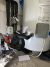
Please can I get some help with a hive install. I have multizone heating, so I have a Hive dual channel receiver and a single channel receiver. This has been installed since 2017 and working without issue. I have a hot water tank upstairs with ZA5 valves for the upstairs and downstairs central heating.

I haven’t used the central heating since the start of summer, fired it up the other day and the downstairs radiators aren’t working. To clarify, the hot water and upstairs radiators do work. The downstairs radiators use the dual channel receiver.

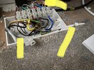
I assumed it was the motorised valve, but I have changed that and it didn’t solve it. More investigation and I’m pretty sure the downstairs heat On is not getting getting any power. The hive receiver turns green, I can hear the relay in the receiver click, but nothing happens and I don’t ‘think’ I get voltage on the switch wire near to the valve.

I should say, I have builders in at the moment, wish I had tested this before they started working!

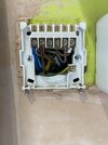
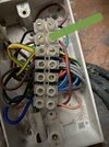
Please can someone confirm that I have this right. In the picture of the hive receiver wiring, number 4 is the heating on and in the second picture, marked green is what I’m sure is the switch wire.
When a call for heating is made, mains voltage should go to number 4 and to the valve. If I get no power to the valve, then I think that either the builders have damaged the physical cable.. yet the permanent live has power.. or the hive receiver isn’t actually switching on number 4 although it looks and sounds like it is.
How can I test the continuity of the cable, could I bridge the permanent live to the switch and make sure the valve operates.. or how can I test the hive receiver? Or am I missing something else.

Thanks,
Chris
 

Attachments

  • IMG_1104.jpeg
    IMG_1104.jpeg
    335.4 KB · Views: 42
  • IMG_1098.jpeg
    IMG_1098.jpeg
    296.5 KB · Views: 54
  • IMG_1119.jpeg
    IMG_1119.jpeg
    341.3 KB · Views: 51
Sponsored Links
Your reasoning sounds good to me. Hive Dual Channel terminal 4 becomes 'live' when the Hive switches on the Central heating. That 'live' is then connected to the 'live' of the motorised valve. The valve winds open and when it's open, an internal switch inside the valve operates to start the boiler & pump.

I would start by using a multimeter and looking for 230V across the motorised valve L & N. If there isn't 230V there, then check the motorised valves N with another known live, such as the permanent L supply to the motorised valve's switch (usually the motorised valves grey wire) If you get 230V then, the N is OK. and it will be a matter of testing the L output from the Hive. I usually connect 2 wires to the N and 4 terminals and bring them outside of the Hive so that the Hive can be replaced on the backplate. Then with the heating set to be 'on' 230V should be present between the two wires. If it is then it will be a matter of checking each connection between the route from Hive 4 to the motorised valve L, until you find where the live disappears.

This assumes that you are competent to be able to do this safely and that you have the correct Hive for the radiators in question. From the content of your post, you seem to know what's what, but it has been know for a user to get them mixed up.
 
  • Thanks
Reactions: CBW
How do you think the builders have damaged the cable?

As for continuity I believe you can trace using brown wire in number 4 and another within the hive backplate, so possibly the earth by disconnecting them, place in terminal strip one for each one and in the wiring center disconnect the ones being tested, and use a continuity tester between the 2 ends. Hope I’ve got that right.
 
Thank you for taking the time to reply. Your suggestions seem obvious now you have told me, but for some reason never entered my head!

As for how do I think the builders have damaged the cable. I actually have decided I don’t think they have damaged it, it’s just the coincidence of they have been doing work and now it doesn’t work.

Thanks,
Chris
 
  • Thanks
Reactions: CBW
Sponsored Links
Hi,
So, going to my upstairs, to the valve which had no power, was a grey cable containing a brown, black, grey and earth. Using the methods described, (thanks) I did some testing and the black and grey cables were fine, however the continuity test on the brown was negative. Maybe the builders have damaged the cable but to damage only the brown seems highly unlikely to me?
Anyway, the builders have installed me a new cable, same colour configuration installed carefully taking out one wire and replacing with same colour. I did the hive end, but the builders did the end into the terminal block up by the valves.
My downstairs radiators now work and the za5 valve is fine. But.. I now have no hot water or upstairs central heating. Same problem, the green light comes on the hive receiver, I can hear the relay tick, but no call for heat or water is actually made. Could this be caused by the new cable not being installed correctly? I just can’t fathom it out.. but feel like I will also have to test the continuity of this ‘new’ cable.

No worries I thought, no hot water isn’t a problem, I will flick the switch on my immersion heater which I haven’t used in the 10 years it’s been Installed, but after an hour, still no hot water. Then I realised it’s the indirect version of the tank, so probably doesn’t have an immersion heater.. any help?
Thanks
 
So, going to my upstairs, to the valve which had no power, was a grey cable containing a brown, black, grey and earth.
That isnt enough cores you need 5 cores for that valve if it requires an earth, are you sure the origional installation wasnt using the green yellow wire as a live ?
 
Sorry, that’s my poor explanation. There are two grey wires which go up to the valves, but only one has been replaced.
 
Sorry, that’s my poor explanation. There are two grey wires which go up to the valves, but only one has been replaced.
Forget about the colours in the grey wires as you call them, they are cables not wires, trace the black cable from the valve and there will be 5 wires in this cable, they are the only colours you can rely on in a heating system

you should have :

Grey = Permanent live and will be joined in the rats nest with 2 other greys
Orange = switched live, this also will be joined with another 2 oranges in the rats nest
Brown = Live that powers the motor to open whenevet that valve is called to operate by the contros
Blue = Neutral
yellow and green = earth

Can you confirm this is the case
 
  • Thanks
Reactions: CBW
Yes, that is the case. Following back from the valve, the brown connects to a blue in the rats nest and goes to the hot water tank.

From the Hive receiver, the grey in number 3, connects in the rats nest to the brown which is also going to the hot water tank.

I get zero volts from N to any of those wires when the hot water is not called, which is as I would expect. When I call the hot water, I still get zero volts from the receiver.
The only place I have voltage is the permanent live showing 249v and the switch showing 30v.

The outputs from the hive receiver work, the hot water worked before they put the new cable in. I think next step would be to test the continuity of the new cable?

Marked in the picture is the grey from Hive, the white cable going to the cylinder and the brown from the valve.

Thanks
 

Attachments

  • IMG_1183.jpeg
    IMG_1183.jpeg
    395.2 KB · Views: 29
  • Thanks
Reactions: CBW
Yes, that is the case. Following back from the valve, the brown connects to a blue in the rats nest and goes to the hot water tank.

From the Hive receiver, the grey in number 3, connects in the rats nest to the brown which is also going to the hot water tank.

I get zero volts from N to any of those wires when the hot water is not called, which is as I would expect. When I call the hot water, I still get zero volts from the receiver.
The only place I have voltage is the permanent live showing 249v and the switch showing 30v.

The outputs from the hive receiver work, the hot water worked before they put the new cable in. I think next step would be to test the continuity of the new cable?

Marked in the picture is the grey from Hive, the white cable going to the cylinder and the brown from the valve.

Thanks
Wiring looks wrong imo. That grey wire from the flex in connector block looks like it joins with a black direct to orange? Or is that the black from cylinder thermostat? Nothing seems to be motoring the valve over. The brown wire (for the valve) goes to the cylinder thermostat but that’s it, nothing is telling the brown to energise.
 
I’ve had another look, the grey cable from the hive receiver, goes into that block where it connects to the brown in that white flex to the cylinder. I assume It then comes out of the cylinder on the blue, which connects to the brown of the valve.

The sequence makes sense but have I got it right, the hive turns on the hot water, the power goes to the thermostat and if the water needs heating, the thermostat sends power the motorised valve to open…?

Thanks
Yes, sequence correct.
 
Hot water and radiators upstairs and downstairs are all now working. However, I don’t understand why!?!

On my new cable which runs from the receiver to upstairs, I knew the brown worked. So using that, I joined one at a time the grey and black to test the continuity, all fine.

Knowing this did work, I reconnected the black and grey from the old cable into the rats nest. and it now works!

I can only assume the grey and black in the old cable don’t go straight from the receiver to the rats nest for the valves. But this makes my head hurt.

I could leave it, but feel it’s all a bit of a mess. I have a new cable on which I’m only using the brown. I’ve put the unused wires into a piece of block but there is very little room for it all. Would be nice to figure it out and totally stop using the old cable and terminate it neatly. Any suggestions welcome
Thanks
 
I get zero volts from N to any of those wires when the hot water is not called,
you should have 240 v constantly no matter what is called for between the greys and Neutral in all 3 zone valve
 
  • Thanks
Reactions: CBW

DIYnot Local

Staff member

If you need to find a tradesperson to get your job done, please try our local search below, or if you are doing it yourself you can find suppliers local to you.

Select the supplier or trade you require, enter your location to begin your search.


Are you a trade or supplier? You can create your listing free at DIYnot Local

 
Sponsored Links
Back
Top