Ideal ES35 Combi domestic Dual Zone, CM907 Stats

Joined
21 May 2017
Messages
30
Reaction score
1
Country
United Kingdom
Hi - need your help please.
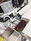
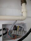
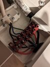
Recently moved into a 2bed terraced house, 7yrs old, which has an Ideal ES35 combi boiler, CM907 stats downstairs and upstairs. Hot water works without a problem. When we put the heating on, via the downstairs stat, all was good, downstairs rads heated up really quickly. However, I woke up around 1:30am to hear the boiler still running - investigation showed that it was the pump that was running, and not the burner. The only way (I could find) to stop the pump was to switch off at the spur, and restart with the boiler dial set to Water, not Water&CH. Engineer came in to sort it out, and was confused by the wiring. He tells me the red loop (left of pic) is where the thermostat controls should be, and also the two unterminated wires should not be that way ! I have looked at next door's, and they do not have the loop, they have what looks to be a stat wire connected.
The 2 zone valves appear to work correctly (I'm told), and I've had a look at the stat connections, which seem to be OK, apart from the 1.5mm twin and earth cable which doesn't appear to do anything ! (see pic)
Previous owner swears blind that he's never had any issues with the CH, and that no-one has ever touched the boiler. Jury is still out on that one.
In my (uninformed) opinion, either someone has been messing about, or it has been improperly installed (or I simply don't understand correctly - which is why I post this)

Please can someone make sense of this for me, before I go back to the builder.

Very much appreciated :)
 

Attachments

  • Combi wiring.jpg
    Combi wiring.jpg
    237.9 KB · Views: 31
Sponsored Links
Engineer came in to sort it out, and was confused by the wiring. He tells me the red loop (left of pic) is where the thermostat controls should be, and also the two unterminated wires should not be that way ! I have looked at next door's, and they do not have the loop, they have what looks to be a stat wire connected.
That all sounds right to me. The loop is only fitted when there aren't any external thermostatic controls used. It is labelled 'room stat / timer'

How it should work is that the two thermostats are each connected to a motorised valve, when heating is required the thermostat opens the valve. When the valve is opened, inside it is a small switch that should be connected to the two boiler terminals with the red loop in this switch operates to start the boiler and pump when the valve is fully open.

I suspect the switches from the motorised valves are connected to the other end of the black and grey wires, and that one of the switches has failed, so someone has removed the wires and inserted the link. If so, what will happen is that the thermostats will be opening and closing the valves so the radiators will be coming on and off as they should, but the boiler and pump are running continually.

investigation showed that it was the pump that was running, and not the burner.
With the motorised valves closed, because no hot water is being circulated around the radiators, no heat will be being lost, the boiler will reach its operating temperature and shut its burner down, meanwhile the pump will continue.

If you can find what the other end of the grey and black wires are connected to, I think you will find your answer.
 
Firstly, many thanks for getting back me - much appreciated.

So, if I put a voltmeter on one or both of the black & grey wire in the boiler, I should get volts when the stat calls ? I understand that one of them may not work, if indeed the loop was lobbed in there because of a failed switch, but just want to check this is a valid test. If this checks out, then it indicates the motorised valve switch needs looking at (do I have that right ?)
Trying to get an electrician in (I was many years ago, but probably forgotten most things now), and just want to give him as much info as I can.

Once again - many thanks
 
So, if I put a voltmeter on one or both of the black & grey wire in the boiler, I should get volts when the stat calls
To test with a multi-meter you are simply testing the end switch on the zone valves, but it sounds like these have been disconnected in the wiring centre, or they would have to have been isolated at the boiler end as they may have 240V some dont but most do, post a pic of your wiring at the wiring centre, it will probably be next to the zone valves, as @stem I think you have a fault with one of the zone valves and someone has removed the correct wiring and put that link it to get the heating to work, more pics of everything and we will be abale to advise further
 
Sponsored Links
Excellent - here's what I believe to be the wiring centre...
 

Attachments

  • Diverters & connections.jpg
    Diverters & connections.jpg
    187.1 KB · Views: 23
  • Stat connection centre.jpg
    Stat connection centre.jpg
    163.3 KB · Views: 25
It's a bit hard to tell what goes where from a photo. This might help.

123.jpg


I would expect the unconnected grey and black wires from the boiler end, to be connected to the motorised valve orange and grey wires of both valves.

No idea about the unconnected twin and earth, do you know where it goes?
 
  • Thanks
Reactions: CBW
It's a bit hard to tell what goes where from a photo. This might help.
Sorry, picture isn't great. The two orange wires connect to a black wire. The cable that goes into the boiler is 4 core & earth, so my guess is that the black wire from the connection centre is joined (somewhere) to the black wire in the 4core (maybe at the fused spur?)
I believe the black wire in the combi originally had some electricians tape on it (not the best termination!)
 
This is a picture of next doors boiler - they have the same 2 zone 2stats setup.
It's slightly different.....but matches up with what you're saying. I didn't want to jump to conclusions without knowing how to test & prove.
 

Attachments

  • combi wiring next door.jpg
    combi wiring next door.jpg
    153.1 KB · Views: 17
The cable entering the boiler is 5 core flex, not 4 core and earth. I would imagine that one wire sends a live voltage out and the other live return, so hopefully not dangerous
 
That photo is more what I would expect to see. The vacant terminal on the left just means that they have picked up the live supply from elsewhere, probably the wiring centre which is quite common. Only the switched live is returned to the boiler.
 
I would imagine that one wire sends a live voltage out and the other live return, so hopefully not dangerous
Nice one - so I should get volts when the stat opens the valve. Thanks (y)
 
If I were testing your installation, I would attach a multimeter set on 'resistance' to the grey and black wires, then operate the upstairs and downstairs valves individually using the thermostats. When either of the valves are wound fully open (takes a few seconds) there should be no resistance measured.

NOTE: To be safe I would do the test first with the multimer set to 'ac voltage' and using a known neutral or earth, check that neither of the wires become live at anytime during the test.

Nice one - so I should get volts when the stat opens the valve. Thanks (y)
You might not though, because as your installation has two disconnected wires I suspect it originally picked up the live from the boiler, not from elsewhere.
 
NOTE: To be safe I would do the test first with the multimer set to 'ac voltage' and using a known neutral or earth, check that neither of the wires become live at anytime during the test.
Exactly what I've done. The black wire shows 243 volts when the stat calls, and nothing (not zero, but very low volts) when the stat is switched off. The grey or violet wire shows very low volts regardless of the stat.
So, I'm guessing that black is switched live and grey or violet is return/neutral.
Is the next stage to connect the black wire to the boiler in the connector are marked thermostat, removing both ends of the red loop ?
Usure as to what happens with the grey wire.
 
The black wire shows 243 volts when the stat calls
Have you tried it with both thermostats, one at a time? If both valves are providing 243V, it begs the question as to why the 'modification' to bypass the external controls with the wire loop was made in the first place.

Is the next stage to connect the black wire to the boiler in the connector are marked thermostat, removing both ends of the red loop ?
Picking up the live from elsewhere would appear from the photo how your neighbours has been connected, and is one of the options shown in the Ideal manual. I've added the second motorised valve switch to their diagram as yours has two motorised valves.

abc.jpg


I'm guessing that black is switched live and grey or violet is return/neutral.
From what you've described, the black wire would appear to be the switched live (also known as 'live return') I can't guess what the grey wire is without physically tracing it to its origin to know what the other end is connected to.

As there were two unconnected wires at the boiler I was expecting it to should have been....

abcd.jpg


So, the unused grey wire remains a mystery for the moment.
 
Have you tried it with both thermostats, one at a time? If both valves are providing 243V, it begs the question as to why the 'modification' to bypass the external controls with the wire loop was made in the first place.
Yes indeed, and both stats give volts. Also, with the boiler switched on, turning up the stat does not fire the boiler. It seems that the boiler is fired only on the temperature of the water in the pipes. And the pump just keeps going !
So I can't think why anyone would take out the stats and return it to the way the boiler was when it was delivered - any ideas ?
 

DIYnot Local

Staff member

If you need to find a tradesperson to get your job done, please try our local search below, or if you are doing it yourself you can find suppliers local to you.

Select the supplier or trade you require, enter your location to begin your search.


Are you a trade or supplier? You can create your listing free at DIYnot Local

 
Sponsored Links
Back
Top