Hello again,
I have now had a closer look at the light fitting wiring, which is actually working,
but I'm a bit confused. The switch contains two wires, a red and a black, with the black going to L1. I'm happy about that, although I thought the black wire should have a bit of red tape on it....has that gone out of fashion now?
Then there are 2 cables coming into the light fitting, which I guess is 1 from the switch and one from the circuit, assuming this is the last light fitting on the circuit.
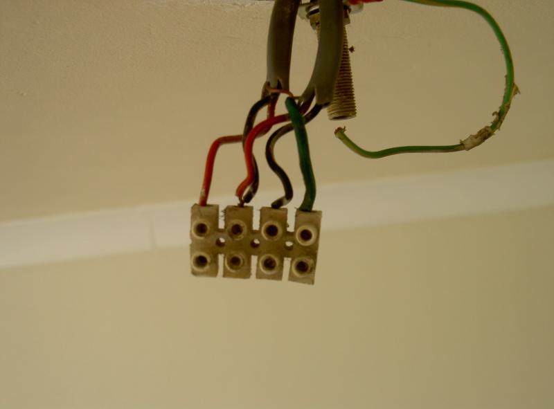
The earths are all together, but then things start to go a bit loopy....the light fitting brown (live) flex seems to be teamed up with a red wire. I would have expected a (switched) black cable to go to the live flex???
And there is one black cable going in with the blue (neutral) flex, with the red wire from that cable joining up with the black wire from the other cable.
Does that make sense?
I thought the neutrals should be in one terminal, the earths in another, the lives in another, and the switched live going to a terminal with the live flex for the light.
So why have I got a red cable joined in a terminal with my brown flex from the light?
Cheers
Trev
I have now had a closer look at the light fitting wiring, which is actually working,
but I'm a bit confused. The switch contains two wires, a red and a black, with the black going to L1. I'm happy about that, although I thought the black wire should have a bit of red tape on it....has that gone out of fashion now?
Then there are 2 cables coming into the light fitting, which I guess is 1 from the switch and one from the circuit, assuming this is the last light fitting on the circuit.
The earths are all together, but then things start to go a bit loopy....the light fitting brown (live) flex seems to be teamed up with a red wire. I would have expected a (switched) black cable to go to the live flex???
And there is one black cable going in with the blue (neutral) flex, with the red wire from that cable joining up with the black wire from the other cable.
Does that make sense?
I thought the neutrals should be in one terminal, the earths in another, the lives in another, and the switched live going to a terminal with the live flex for the light.
So why have I got a red cable joined in a terminal with my brown flex from the light?
Cheers
Trev