Negative head switch for shower pump???

Joined
26 Nov 2009
Messages
4
Reaction score
0
Location
Yorkshire
Country
United Kingdom
I have fitted a Salamander CT75 shower pump for my thermostatic shower and the only problem is the pump does not start when the shower is switched on. As soon as it runs there is no problem. I have been told that it is borderline negative head and as the pump is virtually new the most cost effective way to cure this problem is to fit a negative head switch rather than buy a new negative head pump. I not too sure how to wire this in and any help or links to wiring instructions would be most appreciated.

Many thanks in advance.
 
Sponsored Links
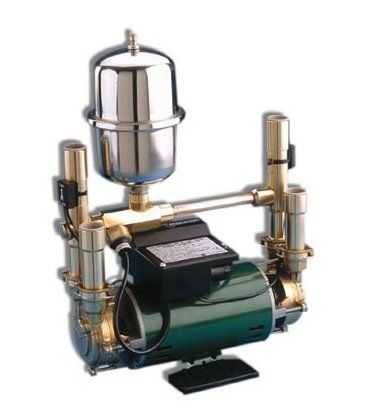
Negative head pumps require a pressure vessel, so I don't think a standard pump can be converted to negative head.

I had to change mine.

An example of a negative head pump with vessel:-


stuartturner_negativeheadtwin.jpg
 
wheres the pump located ?

theres easier ways to increase the min flow than converting the pump to neg head.
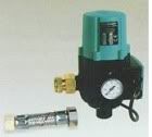
and you can get a conversion kit.
thrcm3.jpg


whats the layout of the pump, shower etc ?
 
Sorry - didn't give all the details
The pump is in the airing cupboard above the HWC approx six inches as there is no room to fit it anywhere else. A Salamander S flange is fitted to the HWC.
From the base of the cold water supply tank to the shower head is approx 800mm.
From the base of the cold water supply tank to the pump is at least 1.8M.
Supply to the pump is in 15mmm pipework as the pump is supplied with 15mm flexible connections.
 
Sponsored Links
That's correct - but even then sometimes I have to leave it for 10-20 seconds.
 
Normally you just wire a normal pull switch in place of the flow switch.... should be in the instructions if it's possible..
 
Thanks very much for the replies there gents - I think I'm going to give one of these switches a try and see if it solves the problem.
 
the issue is with the plumbing/pipework somewhere not a neg head situation.

your not getting 1 ltr min flow on eachside for some reason.

where do the pipes go from the pump to shower ? into loft, horizontal into bathroom etc ?

how long are the pipes from pump to shower ?

have you fitted any isolation valves ?

have you a non return valve on the hot side ?

have you a drawing of the exact layout ?
 
Make sure the 15mm flexi conns aren't twisted. It could look fine from the outer braiding, but sometimes the pipe inside gets twisted- which is exactly what happens to shower head to mixer flexi leads (due to them being moved about a lot), So check that as well.

Since the pump is above the height of the HW tank and 99% of pump makers say place at foot or below HW tank, how is that not a neg pressure situation ?
 
Since the pump is above the height of the HW tank and 99% of pump makers say place at foot or below HW tank, how is that not a neg pressure situation ?

pump & outlets are still below cws at required min distance.

scact.jpg
 
Since the pump is above the height of the HW tank and 99% of pump makers say place at foot or below HW tank, how is that not a neg pressure situation ?
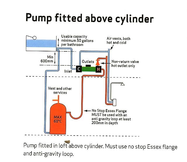
The “head” of pressure is measured from the underside of the cws tank (which feeds the hws tank), not the hws tank itself. Any up & over loops in the delivery lines to the shower head must also run below the bottom of the cws tank (2ft for Salamander) or you will still create a negative head situation. Also pay attention to the need for vents, a non return valve on the hw outlet (as per Seco’s pic) any isolator valves should always be full flow type; gas ball valve are the best IMO as the majority of gate valves will restrict flow.
 
Maybe I am wrong in my understanding of the term "negative head" I take it as meaning the arrangement of pipework and tanks means there is negative pressure on either hot and/or cold water at the inlet to the pump. That the pump must remain primed by the use of non return valves and has to suck water up when started by a switch.

In the diagram shown there is positive pressure on both inlets from the head ( the 600mm between base of tank and pump plus the depth of the water in the tank ). If the inlets to the pump were disconnected then water, hot and cold would flow out of the pipes. So the pump is primed without the need for non return valves.

The problem seems to be that when the shower taps are turned on there is not enough pressure ( from the head of water in the tank ) to create enough flow to operate the flow valve and turn on the power to the pump.

If there is a restriction in the pipe this would also reduce the flow to be inadequate to operate the flow switch.

If the restriction cannot be removed then increasing the head ( and therefore pressure from the cold water tank might be the answer, set the ball cock to fill the tank to a higher level if possible. A test can be made to see if this will work by holding the ball cock down to fill the tank more than normal and letting the water rise as far as the overflow outlet.
 
Maybe I am wrong in my understanding of the term "negative head" I take it as meaning the arrangement of pipework and tanks means there is negative pressure on either hot and/or cold water at the inlet to the pump. That the pump must remain primed by the use of non return valves and has to suck water up when started by a switch.
Technically you’re correct; as long as the highest point in the system remains below the water level there, there will be a positive pressure head but it won’t be enough to trigger Salamander’s flow switches; their choice of terminology. The hw non return valve is fitted on the delivery side of the pump, not the feed.
In the diagram shown there is positive pressure on both inlets from the head ( the 600mm between base of tank and pump plus the depth of the water in the tank ). If the inlets to the pump were disconnected then water, hot and cold would flow out of the pipes. So the pump is primed without the need for non return valves.
Seco’s diagram is actually Salamander’s diagram taken from their installation manual; it is they who recommend the non return valve on the HW only & who state a minimum of 600mm; it varies depending on manufacturer so, presumably, some have more sensitive flow switches than others. The un-pumped flow rate must be a minimum of 1 litre/min to activate the flow switches.
The problem seems to be that when the shower taps are turned on there is not enough pressure ( from the head of water in the tank ) to create enough flow to operate the flow valve and turn on the power to the pump.
Correct.
If there is a restriction in the pipe this would also reduce the flow to be inadequate to operate the flow switch.
That’s the reason for my note about using non-restrictive isolator valves
If the restriction cannot be removed then increasing the head ( and therefore pressure from the cold water tank might be the answer, set the ball cock to fill the tank to a higher level if possible. A test can be made to see if this will work by holding the ball cock down to fill the tank more than normal and letting the water rise as far as the overflow outlet.
In a situation as per diagram, there is still positive pressure head provided by the distance between the surface of the water in the tank & the highest point of any up & over loops, it’s just all of the above may conspire reducing the water flow below the minimum 1 litre/min required trigger the flow switches. Raising the water level in the tank may just be enough to improve the swich triggering, it's worth a try but maybe unreliable & it's best to start with a corectly installed & plumbed system in the first place.
 

DIYnot Local

Staff member

If you need to find a tradesperson to get your job done, please try our local search below, or if you are doing it yourself you can find suppliers local to you.

Select the supplier or trade you require, enter your location to begin your search.


Are you a trade or supplier? You can create your listing free at DIYnot Local

 
Sponsored Links
Back
Top