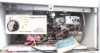
I wonder if anyone is able to help. I have a ServoWarm Elite 50 Boiler . it is over 30 years old , and is extremely reliable and has never really broken down. This is a simple hot water boiler system . with a pump and thermostat all in the housing. there is no room thermostat. so all it does is, send hot water around in a single circuit serving the emersion tank and central heating. The boiler thermostat is controlled by the max//min settings in the honeywell modulec unit and when hot enough the boiler turns off, and on again etc until the timer goes off. then the pump overrun continues for a little while.
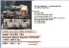
My problem is, the programmer , a Horstmann 424 Emerald ( discontinued ) clock is faulty due to a slipping/worn plastic gear wheel and required manual switching. I need a replacement programmer .. This clock was a bespoke unit for this boiler, with a built in pump over run switch . Horstmann UK recommended a modern version , a 425 Coronet, but it has no pump overrun ( so they cannot advise on it ) . In which case I could just get any single switch timer/programmer for hot water only.. and connect some delay relay unit as pump overrun. Does anyone know if there is such a thing as an external relay / pump overrun unit that can be connected from a new programmer ( any of the above) to the pump?
My problem is, the programmer , a Horstmann 424 Emerald ( discontinued ) clock is faulty due to a slipping/worn plastic gear wheel and required manual switching. I need a replacement programmer .. This clock was a bespoke unit for this boiler, with a built in pump over run switch . Horstmann UK recommended a modern version , a 425 Coronet, but it has no pump overrun ( so they cannot advise on it ) . In which case I could just get any single switch timer/programmer for hot water only.. and connect some delay relay unit as pump overrun. Does anyone know if there is such a thing as an external relay / pump overrun unit that can be connected from a new programmer ( any of the above) to the pump?
Attachments
-
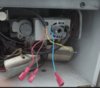
 PROGRAMMER-Horstman-424-Emerald-BURGESS SWITCH V4NT7.jpg169.7 KB · Views: 849
 -
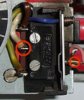
 Z-Horstman Timer 1.jpg80.4 KB · Views: 1,040
 -
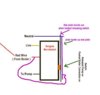
 Z-Horstman Timer 2.jpg94.8 KB · Views: 647
 -
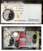
 Z-Horstman Timer 4.jpg91.7 KB · Views: 496
 -
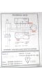 000 SERVOWARD TECHNICAL DATA.jpg236.3 KB · Views: 407
 -
 zz-Burgess Switch circuit.jpg26.2 KB · Views: 415
Last edited:
.jpg")
")
.jpg")