Radial off Ringmain Query

Joined
7 Oct 2013
Messages
8
Reaction score
1
Location
Renfrewshire
Country
United Kingdom
Hi All,

Ive been having a bit of an issue with my extensions electrics, for info the extension was built before I moved in, I reckon it was built around 2000.

The issues I've been having is that there is a phantom voltage on the Earth of 120v on the sockets and 70v on the lights. Ive also noticed that a cheap socket tester shows a live earth/ missing ground which started me on my investigation. I checked all the sockets and traced it to the socket behind the fridge, I reckon this is what is causing my issues as the earth cable doesn't have sheathing and is hard up against the live cable and looks to have sliced into it slightly.

My intention is to replace the 1.5m cable from the previous socket and the socket (its proper old) and hopeful this might sort the live earth / phantom voltage.

What i was also thinking is I thought that any spurs off the ring main with more than one socket had to be fused? In my case this spur has; two double sockets, the lighting (which is fused) and an outdoor socket. What I don't know is if the extension builder extended the ringmain, which I doubt as I can't find any other evidence. So I'm thinking that when I replace the socket, if I don't wire the extension supply back in temporarily (safely terminated) before I turn the power back on if the extension is live then the system is acting as 2 radials and therefore the extension builder has extended the ring main and if it is dead then its an extended spur without a fuse. Does this sound right.

The extension has a beefy old plasma tv and a tumble dryer it so I'm just making sure its safe.

Sorry for the long post and no doubt wrong use of terminology, thanks in advance.
 
Sponsored Links
What i was also thinking is I thought that any spurs off the ring main with more than one socket had to be fused?
Well, they have to be protected somewhere by a fuse/circuit breaker appropriate for the cable size.

So, an appropriately sized fuse/circuit breaker in the consumer unit, or
a Fused Connector Unit on the spur, or
a suitably sized cable for the spur so that it doesn't require an additional fuse.

You mention 1.5mm² cable; that is not likely to be correct in any situation for the ring circuit or the spur.

In my case this spur has; two double sockets, the lighting (which is fused) and an outdoor socket.
Ok, so will have to be as above.

What I don't know is if the extension builder extended the ringmain, which I doubt as I can't find any other evidence. So I'm thinking that when I replace the socket, if I don't wire the extension supply back in temporarily (safely terminated) before I turn the power back on if the extension is live then the system is acting as 2 radials and therefore the extension builder has extended the ring main and if it is dead then its an extended spur without a fuse. Does this sound right.
Hard to say.

If you don't know how to find out, then you need an electrician.
 
Thanks for the quick reply, I was referring to replacing a length of cable at 1.5m in length, it looks to be 2.5mmT+E. apologies for not being clear
 
The issues I've been having is that there is a phantom voltage on the Earth of 120v on the sockets and 70v on the lights.
How are you measuring this?

Ive also noticed that a cheap socket tester shows a live earth/ missing ground which started me on my investigation.
That could be a cause.

I checked all the sockets and traced it to the socket behind the fridge, I reckon this is what is causing my issues as the earth cable doesn't have sheathing
Not the end of the world.

and is hard up against the live cable and looks to have sliced into it slightly.
Ok. That's not good - repair it and test again.

My intention is to replace the 1.5m cable
As I said 1.5mm² doesn't sound good.

from the previous socket and the socket (its proper old) and hopeful this might sort the live earth / phantom voltage.
Let us know if it does.
 
Sponsored Links
Right, so if the spur is 2.5mm² on a 32A ring circuit, then it should have an FCU with 13A fuse before the first socket.

OR

The whole spur could be wired in 4mm² cable which can take more than the 32A.
 
Ok. That's not good - repair it and test again.

I will repair and see if it will fix the earthing issues. this was my main concern as the trip button on the socket tester doesn't trip the RCD in the CU. The rest of the house is fine, only the extension.

As for the Spur FCU, I was hoping you would say that, I had in my head it could be dangerous if the tumble dryer was on at the same time the outside socket was being used for a lawnmower. I will confirm the cable size when I do the repair to the socket/feed, I do suspect its 2.5T+E though.

Thanks for your time mate.
 
As for the Spur FCU, I was hoping you would say that, I had in my head it could be dangerous if the tumble dryer was on at the same time the outside socket was being used for a lawnmower.
Mmmm. The rules are not exactly logical.

You are allowed one double socket without the fuse so you could have TD and LM going at the same time anyway - not actually dangerous as the 2.5mm² cable can handle the maximum 26A (2 x 13A) but 13A is the largest sized fuse that goes in FCUs.
You could have a 26A FCU if there was such a thing.

If only they would just state that ring circuit spurs should be of 4mm² cable and capable of handling the 32A then all the confusion and queries would go away.
Understood.

I will let you know how I get on when the cable/socket repair and if it resolves the other issue.

Thanks again
 
Before hacking into walls to replace legs of a ring final circuit, open up the points connected to the leg you suspect is faulty, then disconnect the faulty ends and replace them with a new piece just run temporarily between the two points.

Does this rectify the issue?

If not, it's best to split the ring somewhere in the circuit and test each leg having disconnected them at the consumer unit. If you need to do a live test, reconnect one leg to the supply at the CU. If there's a fault somewhere, then one leg should read faulty and the other should read good.

Then you can continue to split down the faulty leg to pinpoint the issue.
 
The problem is we tend to call things rings, and ring mains when in reality they are not ring finals. It is just what we expect to find.

A ring needs cable able to take 20 amp, often it can take more, but that's the lower limit, and the lower limit is 2.5 mm² unless using mineral insulated cable, maximum fuse/MCB/RCBO size of 32 amp, and it is rare to find anything lower.
Since called a ring final, you can't have another circuit from it, it is the final circuit, but in real terms we can have fused and unfused spurs, and a fused spur is really a radial final but we can't call it that, as English will not allow a final final, looking at the English language rather than electrical practice.

We can also have radial finals, but unlike the ring final, they can be with multiple cable sizes, and the fuse/MCB/RCBO can be any size up to 32 amp, there is no rule stopping a 6 amp radial, in fact that is what our lighting circuits are.

The problem with the ring final is as you have pointed out, if some one plays, it can become two radials, so if we measure the loop impedance before we start, then we check it is a ring, i.e. line connects to line etc. Then when we finish if the loop impedance is the same, then we know we have not broken the ring, the problem lies in the cost of a loop impedance meter, we can test at the CU, but I am not happy telling some one to delve into a CU.

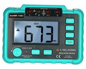
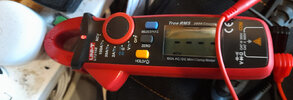
The same applies to other tests, we should measure the insulation resistance, and the earth leakage, and the tripping currents and times for any RCD/RCBO in circuit, it is such a quick test for an electrician, but the DIY guy simply does not have the test equipment, some bits are not too bad, a clamp on able to test down to 0.001 amp AC and DC costs around £35 and a insulation tester the same, the plug in socket tester with loop, unfortunately does not measure below 1.9 Ω and the upper limit with a ring final is 1.38 Ω so although not useless, it does not really test, and no stop watch can measure 40 mS to test a RCD, so the loop impedance tester, the RCD tester and the low ohm meter with at least 200 mA test current are all expensive, not a clue why no cheap versions of the latter.

However armed with £70 worth of test equipment VC60B.jpgTesting for live.jpg I can find most faults, and if not I can borrow test equipment, but even £70 is a lot to spend, and the point is you need to decide is it worth it, or is it cheaper to get some one to inspect and fix it for you?

I assume you have some test equipment already to give us voltages, I have only one tested MCB's trip at rated currents, and that's another story, and in the main I cross my fingers that other protection devices work as they should, from time to time I have tested my RCD's with a proper tester, but if they were swamped with DC so would not work, I am unlikely to know. If the test button works I assume they are OK, however a test button often uses more like 100 mA not 30 mA and really is only the test the mechanics.

So you have unearthed some potential dangerous faults, they may not be dangerous, but without testing we don't know, and the big question is it worth doing it DIY? I would love to sit here and guide you through the testing, but is that really what I should do with such a fault, clearly should not refuse to help, that would be silly, but I should point out the limitations and allow you to decide if you think this is a DIY job.
 
The problem is we tend to call things rings, and ring mains when in reality they are not ring finals. It is just what we expect to find.

A ring needs cable able to take 20 amp, often it can take more, but that's the lower limit, and the lower limit is 2.5 mm² unless using mineral insulated cable, maximum fuse/MCB/RCBO size of 32 amp, and it is rare to find anything lower.
Since called a ring final, you can't have another circuit from it, it is the final circuit, but in real terms we can have fused and unfused spurs, and a fused spur is really a radial final but we can't call it that, as English will not allow a final final, looking at the English language rather than electrical practice.

We can also have radial finals, but unlike the ring final, they can be with multiple cable sizes, and the fuse/MCB/RCBO can be any size up to 32 amp, there is no rule stopping a 6 amp radial, in fact that is what our lighting circuits are.

The problem with the ring final is as you have pointed out, if some one plays, it can become two radials, so if we measure the loop impedance before we start, then we check it is a ring, i.e. line connects to line etc. Then when we finish if the loop impedance is the same, then we know we have not broken the ring, the problem lies in the cost of a loop impedance meter, we can test at the CU, but I am not happy telling some one to delve into a CU.

The same applies to other tests, we should measure the insulation resistance, and the earth leakage, and the tripping currents and times for any RCD/RCBO in circuit, it is such a quick test for an electrician, but the DIY guy simply does not have the test equipment, some bits are not too bad, a clamp on able to test down to 0.001 amp AC and DC costs around £35 and a insulation tester the same, the plug in socket tester with loop, unfortunately does not measure below 1.9 Ω and the upper limit with a ring final is 1.38 Ω so although not useless, it does not really test, and no stop watch can measure 40 mS to test a RCD, so the loop impedance tester, the RCD tester and the low ohm meter with at least 200 mA test current are all expensive, not a clue why no cheap versions of the latter.

However armed with £70 worth of test equipment View attachment 303936View attachment 303937 I can find most faults, and if not I can borrow test equipment, but even £70 is a lot to spend, and the point is you need to decide is it worth it, or is it cheaper to get some one to inspect and fix it for you?

I assume you have some test equipment already to give us voltages, I have only one tested MCB's trip at rated currents, and that's another story, and in the main I cross my fingers that other protection devices work as they should, from time to time I have tested my RCD's with a proper tester, but if they were swamped with DC so would not work, I am unlikely to know. If the test button works I assume they are OK, however a test button often uses more like 100 mA not 30 mA and really is only the test the mechanics.

So you have unearthed some potential dangerous faults, they may not be dangerous, but without testing we don't know, and the big question is it worth doing it DIY? I would love to sit here and guide you through the testing, but is that really what I should do with such a fault, clearly should not refuse to help, that would be silly, but I should point out the limitations and allow you to decide if you think this is a DIY job.
I get your point, I really do. But I think you might have missed the part that I said I couldn’t trip the RCD within the CU, my basic equipment has valid dangerous concerns. It lead to me to having a look behind the sockets and identified some fixable repairs.

I have a little knowledge and the spur didn’t look right so I was running it by you guys before calling in a suitable professional, I don’t doubt they will have all the fancy toys you mention above.
 
Sorry missed the bit about not tripping the RCD, we have some CU's called high integrity, not a clue how the got the name, but they have three neutral bars, two RCD's feed two of the neutral bars, and the third has RCBO's for critical equipment of course MCB's could be fitted, and today often the SPD uses those slots.
1684634801750.png
The units are still available, in fact when I looked for the picture, I found some boards being sold with type AC RCD's and also with 63 amp RCD's I am sure there are applications where they can be used, but it must be rare today. But at £54 with "100A Main Switch, 2 x 63A 30mA RCD (Type AC) c/w 10 MCB's (3x6A, 2x16A, 4x32A, 1x40A) Fitted" it must be a temptation to buy and use them, seem to remember back in 2019 I paid around £300 for mine, and used a cheap make, FuseBox.

It is hard to critise some one else's work. Although it may not be compliant with current BS 7671 that does not make it potentially dangerous, and there is no problem using a 63 amp RCD with a 60 amp DNO fuse, and we are not permitted to draw the fuse to check on the size. So if an old Wylex fuse box was fitted with a 60 amp main isolator then this could be replaced with a CU with 63 amp RCD's. The DNO should have never fitted over a 60 amp fuse. Not sure I would want to rely on that?

It raises the question should we trust that those before us have followed the rules? Some times we have no option, but I remember finding a 4 mm² radial on a 32 amp MCB and half way along it's length I found it had been split and 2.5 mm² fed a number of sockets in the room, then it returned to 4 mm² and this was in premises where a full time electrician was employed, so unlikely a DIY job, clearly the electrician had not tested when he did the work, or he would have known it was not a ring final.
 
Your phantom voltage on the earth points to it not actually being connected to anything.
Your socket tester failing to trip an RCBO/RCD would also suggest that.
As suggested, before hacking into walls have some more faceplates off and check all connections. While you're doing that you can map out the circuit(s).
Yea, I should add that I have checked every socket in the house to find what fed the extension and to check the terminals, the last one to check was the one behind the fridge which had the issues which also was the feed to the extension.

To be honest if this doesn’t fix it I’m calling someone in, it’s the limit of my capability. I’d love to draw the circuit(s) especially due to the amount of change to the house over the years but I don’t have the kit or knowledge.
 

DIYnot Local

Staff member

If you need to find a tradesperson to get your job done, please try our local search below, or if you are doing it yourself you can find suppliers local to you.

Select the supplier or trade you require, enter your location to begin your search.


Are you a trade or supplier? You can create your listing free at DIYnot Local

 
Sponsored Links
Back
Top