Radiators Heating up when only Water Heating is selected

Joined
22 Apr 2009
Messages
9
Reaction score
0
Location
Cambridgeshire
Country
United Kingdom
I have had this issue for years, and even replacing the three port valve completely did not solve it. Now with the gas prices so high I would like to get to the bottom of the issue.

Could it be some sort of convection causing a reverse flow into certain radiators. I notice that about half the radiators get hot.

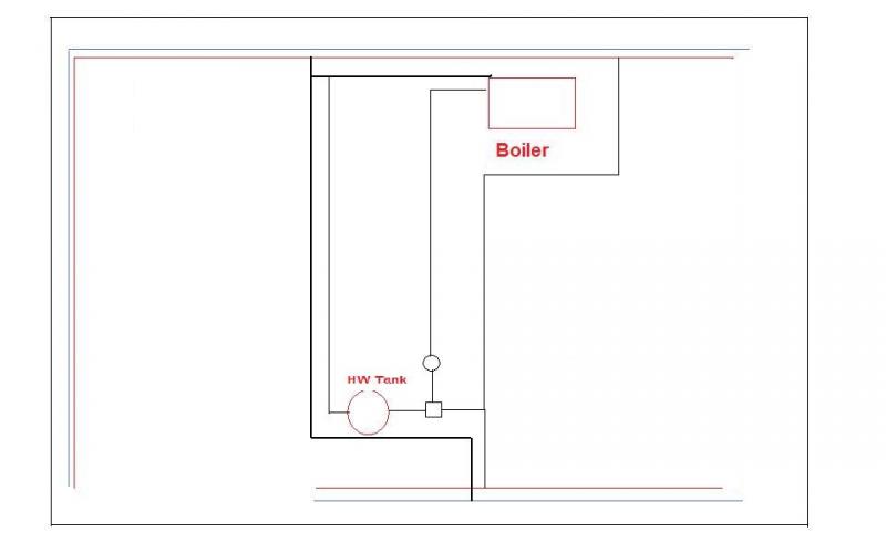
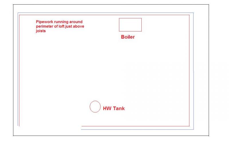
I have a bungalow with all the CH pipes running in the loft, and the individual pipes to radiators drop through the ceiling adjacent to each rad.

All of the rads are equipped with thermostatic valves, but in addition I have a Potterton programmer with temperature set back, so the radiators where the stat is located have either had the thermostatic element removed or fully opened.

I would be grateful for any suggestions as how to (a) find out what is happening to cause them to heat up, and (b) how to remedy the situation.

One idea I had was to find the flow pipes after the "Y" piece and insert solenoid valves here wired to the appropiate contacts on the programmer so that both flow AND return are closed off when the relevant thermostat closes. Surely this would eliminate the issue, however could it cause pressure build up leading to other problems?

Thanks Chris
 
Sponsored Links
That senario would not usually create any thermal convection.

Lets start at the beginning, is the system balanced or are all the rad valves wide open?

Is the pump on setting "3" or on "2" or "1"

Tony
 
reverse circulation is useally caused when your returns from the rads don't join together before the main return.
 
That senario would not usually create any thermal convection.

Lets start at the beginning, is the system balanced or are all the rad valves wide open?

Is the pump on setting "3" or on "2" or "1"

Tony

I believe the system is balanced....
However I did it myself after having to rerun some of the pipework in the loft because of a loft conversion. I didn't know about the temperature drop, so it has all been set up by best guess.

The Plumber had been told to run the pipework around the perimeter of the loft because we knew we would be having a conversion later, but as the CH installation "happened" whilst the house was unoccupied before we moved in - the system had been completed and commssioned by the time we noticed that it had not been done as we requested.

The system is circa 1991, has a Ideal Classic boiler with a traditional tank and expansion with 6 radiators. The controller is a Potterton EP 2000 which originally just ran the Central heating non stop with a cylinder stat to control the water. It relied on Thermostatic valves for the temperature control.

Later I installed first a standard stat in the living room, latterly I installed a Honeywell CM67 and set the Potterton onto continuous on the CH and let the Honeywell fully control the central heating. The rads where the Honeywell is have had the thermostatic capsules removed.

The pump is installed near the tank and triport valve and is set on 1. I have a distinct suspicion that the "T" on the other end of the flow is on the opposite side of the house. The boiler is in the kitchen and the flow and returns go up into the loft and are sort of "H" shaped in that there are 22mm main flow and return running along the front and back of the bungalow with 2 connecting pipes that connect them which run from front to back about half way along and run under the floor of the loft conversion. So the return (I think this is the one with the pump in it) runs all the way from the tri valve in the airing cupboard at the front of the house, up into the loft, across a couple of joists and then ducks between two joists and runs to the rear were it ascends, turns ninety degrees and runs over the joists along the perimeter until it reaches the boiler where it descends to the unit. The flow however ascends from the boiler runs along the perimeter to where the other pipework passes under the floor, and then splits between HW and CH, the CH then splits again and supplies the 22m runs at the front and rear of the bungalow, whilst the HW pipe descends under the loft floor and then runs to the front where it again ascends slightly passes over two or three joists and then descends through the ground floor ceiling into the airing cupboard.

I understand now that having the sort of double dip in the pipes probably causes a lot of air pockets as I had all sorts of issues which culminated in me adding short vertical pipes at front and rear of the loft with air bleed screws at the top of them. I regularly get air out of these when I go into the loft at approximately six monthly intervals.

There is probably also an issue with the header tanks as originally the plumber used the existing platform which was attached to a chimney breast right up in the pitch of the roof. the tanks were both relocated into the eaves of the bungalow to make way for the loft rooms, and the bottom of the tanks is probably only 8 feet off the ground floor level.

Flows from the hot taps are reasonably acceptable.

I suspect that we would be better off long term to rip out all this plumbing and change to a pressurised system, as when we tried radiators in the loft rooms they just didn't work, and I removed them. No doubt although I bought very low ones the top of the radiator was probably no more then 80-100mm below the water level in the expansion tank.

We certainly cannot afford to take the drastic action above so I wondered what other less dramatic actions we could take to rectify the situation?

Sorry about the long post.

Thanks Chris
 
Sponsored Links
I have tried to create a pipe layout just showing the main structure without showing where the radiators are.


The vertical pipes one of which is illustrated as bold are running between the joists and about 50-75 mm lower than the red and blue 22mm flow and return to the radiators which lay across the joists of the loft conversion. Is this an issue?

If it was I guess I could replumb the loft pipewor like this, however what would then be the best way to interconnect the HW and CH pipework together, as the Y valve is in the airing cupboard immediately adjacent to the cylinder and pump.

[/img]
 
I am disappointed that no one has replied.

I was hoping that someone more knowledgeable than I would have some suggestions as to how I could re arrange the pipework in the loft so as to prevent the backflow convection that (I am assuming) is causing the radiators to sometimes heat up when the HW only is selected.

Thanks Chris
 
TBH, I cannot quite fathom your drawings :confused:

If the primary F & R ar taken from the boiler to the airing cupboard, then all the returns taken back to there as well, I cannot see you will get any reverse circulattion.
 
TBH, I cannot quite fathom your drawings :confused:

If the primary F & R ar taken from the boiler to the airing cupboard, then all the returns taken back to there as well, I cannot see you will get any reverse circulattion.

I think my returns join at the boiler side of the house. :)

I am going into the loft and will trace the pipes to figure out where exactly the HW joins the CH on the return

Chris
 
However I did it myself after having to rerun some of the pipework . You are a WUM. :rolleyes:
 

DIYnot Local

Staff member

If you need to find a tradesperson to get your job done, please try our local search below, or if you are doing it yourself you can find suppliers local to you.

Select the supplier or trade you require, enter your location to begin your search.


Are you a trade or supplier? You can create your listing free at DIYnot Local

 
Sponsored Links
Back
Top