Ring doorbell Friedland chime wiring

Joined
8 Jan 2017
Messages
7
Reaction score
0
Country
United Kingdom
Hi

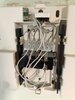
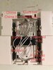
I’m trying to connect 2 Ring wired doorbells to a chime. Or rather, bypass the chime on the doorbells.

The chime is a Friedland 454. I currently have a standard rear and a front doorbell, both work ok.

In the chime, the wires are currently connected to terminal numbers as follows:

0 - 3 white wires
1 - 1 black wire
2 - No wires
3 - 1 red wire, 1 white wire

Could anyone please help in terms of which terminals I need to connect the Ring jumpers to for front and rear door bells?

I’ve looked at various diagrams and my chime wiring doesn’t make any sense at all.

Thanks
 

Attachments

  • FB7C485A-A0FA-4E48-B336-4B2B0E100037.jpeg
    FB7C485A-A0FA-4E48-B336-4B2B0E100037.jpeg
    204.7 KB · Views: 223
Sponsored Links
Can you connect two ring doorbells to one chime? I would check the instructions for that. As for the wiring, its anyones guess. You appear to have three sets of bellwire leaving that chime. Do you have three buttons? An additional chime? I'm taking the red and black to be your permanent feed in.
 
I thought the red and black were the solenoid wires.

Doesn't the front door push make a different sound to the back door push?
 
Sponsored Links
Where the three whites are at Terminal 0, I imagine one wire to be a feed in, one wire to feed the front push, one wire to feed the back push.

What's confusing is it's not necessarily the positive that gets 'switched' at the pushes, it may well be the negative.
 
What are the connections at the very top? Presumably this interrupts one of the wires going to one of the pushes.

Is this what makes the ring tone different to differentiate between the front and back door?
 
I think you’re right about connections to 0.

The 2 connections at the top left. One says A and the other B.
 
Based upon one of the cables to 0 being from the transformer and the cable being marked red by the installer, I believe the other transformer cable, marked red, is going to terminal 3.
 
That might make sense, that could mean terminals 0 and 3 are the supply terminals from the transformer (polarity never really an issue with doorbells),
 
Could the two top terminals be switched wire front door, switched wire back door?
 
Yes, I’ve marked up the attached photo. Does this look right?
 

Attachments

  • 9957C67F-6C75-4F4C-B912-AA125D031E18.jpeg
    9957C67F-6C75-4F4C-B912-AA125D031E18.jpeg
    211.4 KB · Views: 379
That's what I am assuming, yes.

I suppose disconnecting just one of the two top wires, and pressing the pushes, should give an indication of what's going on.
 
I removed the wire from the terminal I marked chime A and the front doorbell loses power, so the theory seems correct.

In order to install the Ring to front doorbell do you think I need to install the jumper wire between chime A and the terminal marked 3? And for the rear doorbell, jumper between Chime B and 3?

I'm not sure. If you look at my current thread on connecting existing or even replacement doorbells to Ring doorbells, it seems it may not even work.

It appears if you can get a regular doorbell to work in conjunction with a Ring system, it may not work for long.

I am hoping to get further ideas on my thread, so we may be able to help each other :D.
 

DIYnot Local

Staff member

If you need to find a tradesperson to get your job done, please try our local search below, or if you are doing it yourself you can find suppliers local to you.

Select the supplier or trade you require, enter your location to begin your search.


Are you a trade or supplier? You can create your listing free at DIYnot Local

 
Sponsored Links
Back
Top