The Dark Art of Open Vented Gravity Flow Systems

View media item 32488
No injector tee. There is a high limit stat on the gravity. Vent is on the primary as shown in the drawing. No vent on gravity.

Picasso - Albion Centurion cylinder. coils are small bore than the 1" which is feeding them.
 
Sponsored Links
are those nail clips tacked straight onto breeze block and mortar?
You might be pulling those walls off to repair some leaks in 10yrs time.
 
Would putting a vent on the gravity help circulation?

The gravity circuit should rise directly from the boiler to an open vent. Its possible that the alternate boiler tapping being used for the vent is adequate.

This is so that if too much heat is being produced then the water can be boiled off at the vent.

If the cylinder coil is not at least 28 mm then even if there was a gravity flow little heat will be transferred.

Tony Glazier
 
Sponsored Links
The safety aspects are probably satisfied if only one connection is going to the vent depending on manufacturer's instructions.

Venting the gravity circuit is the normal way to connect it though.

Not venting the gravity circuit means that adequate provision needs to be taken to prevent air collecting there.

Tony
 
Open vent

The arrangement you have shown will satisfy the general safety aspects, however the systemlink unit has auto vent facility, moving the open vent to the gravity side would eliminate the need to attend to any venting issues that might arise over time.
By that I mean that auto air vents [assuming you have one fitted on the gravity side] could fail on a solid fuel system due to occasional excessive temps, the internal floats and valve arrangements are usually plastic! But not all are so worth a check on that one. Personally I would have done it the other way round.

Cylinder coil

Given that you have a gravity system I would have used the middle coil. This would have allowed for grater dissipation of the solid fuel boiler temps to a larger hot water storage, this would assist the poor circulation by increasing the temp differential between the flow and return.

Limit Stat
The use of is good.

Injector tee.
I would alter the system to incorporate this as it will ensure / induce circulation on the gravity side when the heating is on maximising your heat usage from the solid fuel. [I presume this is a cheaper fuel source]

Consider the introduction of a heat sink in the gravity circuit. This will have two advantages,
1 it will help to dissipate excessive heat along with the hi/limit stat.
2 it will also increase the temp differential and assist in improving the circulation.

or consider the pump suggestion on the return of course.

It is probably to late to learn that an old rule of thumb was 1/2 yard run for every yard rise on a gravity circuit would usually keep you out of trouble.
or do the clacs on the system.

hope thats of use.
 
Assuming the pretty drawing is as fitted, I wouldn't expect it to work. :eek:

1. the top of the cylinder will always be hotter than the gravity flow unless it's near boiling.

2. the bottom coil should be used for the gravity, or the middle coil at a pinch

3. there's no provisions to vent the primary circuit of air.

4. the cold feed and vent must be on the gravity circuit.

5. there should be c ross flow across the boiler.
 
Picasso - Albion Centurion cylinder. coils are small bore than the 1" which is feeding them.

probably your answer. seen quite a few cylinders that have been changed on a gravity circuit. not work. due to part l cylinders using a more resistant coil.
 
I'm surprised no one has questioned the cold feed which is impeded with valves and a circulator!

Also I don't see this schematic on systemlinks website which shows the cold feed/vent arrangement connected on the gravity circuit.
 
*Assuming the pretty drawing is as fitted, I wouldn't expect it to work.
*Also I don't see this schematic on systemlinks website which shows the cold feed/vent arrangement connected on the gravity circuit
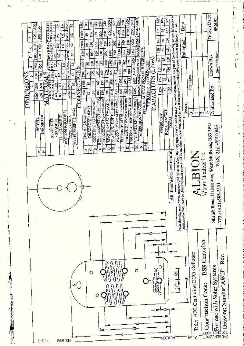
The pretty drawing was drawn by Systemlink

*the bottom coil should be used for the gravity, or the middle coil at a pinch
I should clarify that the top and middle coils are intertwined in the cylinder, not at different levels as shown by the drawing. Attached drawing, number 5 1800x450
*there's no provisions to vent the primary circuit of air.
The vent is on the primary circuit. The Systemzone box has an auto air vent.

* the cold feed and vent must be on the gravity circuit.
Good point. The water cannot expand to begin circulating.
*there should be cross flow across the boiler.
There is cross flow. This drawing omits that detail.

*I'm surprised no one has questioned the cold feed which is impeded with valves and a circulator!
Nope - gravity circuit has no valves, circulators, pumps or anything on it. As shown in the pretty drawing.
 
gravity circuit has no valves, circulators, pumps or anything on it. As shown in the pretty drawing

It also has no cold feed or vent fitted as Doitall has already pointed out.

Systemlinks drawing is flawed as the cold feed should be unrestricted through open bore pipe.
Hardly inspires confidence in their design abilities.
 
Ehh. the cold feed is open bore pipe. There is a valve on the pipe in the attic, but let's not drift here. Gravity or lack of it is the order of the day.
Thanks for repeating what has been said (again).
The message sank in a while ago - vent the grav circuit !

So that's it sorted then? pump it.
 
Ehh. the cold feed is open bore pipe

You have a circulator and two pump valves fitted.
What happens when someone changes the pump and forgets to open the valves or the water boils off quicker that make up water can be replensihed through the restrictive channels in a circulator?

Its not how solid fuel is installed in the UK and I appreciate regulations may differ in Ireland but the physics remain the same.

Thanks for repeating what has been said

Any amount of repeating I'm beginning to think will not get through to you. But you do it your way. A more experienced operative would have spotted the flaw immiediately.
 
The cold supply (unrestricted) is directly into the primary circuit - in drawing and in the real job.
I appreciate your concern about the 'what if' element of the design, but there is one person only ever going to be at the system - me.
The flow and returns for the stove out of the 'circulator' are 1".
The systemlink is more of a neutraliser than circulator.
Yes the zones taken off the unit are circulators when pumped, but they are independent of the stove primary and gravity circuit.
It has internal baffling to stop flows mixing (as I am sure you know)
http://www.stovesonline.co.uk/wood_burning_stoves/SystemZone.html
Link shows internal baffle structure.
But if you look at the right of the drawing where the stove primary is, it comes in and out with nothing restricting it. Yes I do agree about the stove circ.pump, if it did fail or get the valves left shut.
And I do see the difference between my system design and this one..
http://www.systemlink.ie/images/stories/systemlink/Schematics/IME01011111.pdf , and where the contradictions of my design begin..

And yes a more experienced operative would spot things. That's another overstated remark I don't need to hear. Why do you think I am here?. Stating the obvious - I am NOT experienced.
 
Ehh. the cold feed is open bore pipe. There is a valve on the pipe in the attic, but let's not drift here. Gravity or lack of it is the order of the day.
Thanks for repeating what has been said (again).
The message sank in a while ago - vent the grav circuit !

So that's it sorted then? pump it.

You ain't allowed to pump the gravity circuit

You need an open vent on the gravity flow connected to the highest point, as an absolute minimum.
 

DIYnot Local

Staff member

If you need to find a tradesperson to get your job done, please try our local search below, or if you are doing it yourself you can find suppliers local to you.

Select the supplier or trade you require, enter your location to begin your search.


Are you a trade or supplier? You can create your listing free at DIYnot Local

 
Sponsored Links
Back
Top